

A tapered bore bearing never creates its operating fit on diameter tolerance alone. Pushing the inner ring up a tapered journal or adapter sleeve expands the inner ring radially, reducing the bearing’s radial internal clearance. Getting that interference right starts with recognizing which taper ratio the bearing actually uses: 1:12 (suffix K) or 1:30 (suffix K30).
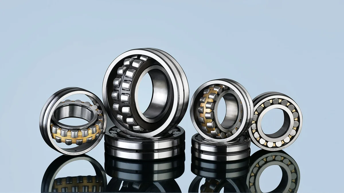
Mixing those two tapers on a rebuild bench, or driving a 240/241 bearing with rules meant for a 222/230 bearing, leads to two opposite failures: cracked inner rings from excessive hoop stress, or inner-ring creep that scores the sleeve and shaft journal within weeks.
Why 240 and 241 Series Use 1:30 (K30) Instead of 1:12 (K)
Most standard spherical roller bearing series—including 222, 223, 230, 231, 232, and 239—use a 1:12 tapered bore (designated K). Wide, thin-to-medium cross-section series—specifically 240 and 241—use a much shallower 1:30 tapered bore (designated K30).
The reason is axial geometry over a wide seat. A 24036 CA/W33 measures 180 x 280 x 100 mm, and a 24152 CA/W33 stretches to 260 x 440 x 180 mm (109 kg). On a 180 mm wide seat, a steep 1:12 taper would leave a large wall-thickness variation from the small side of the inner ring to the large side, forcing heavy press forces and uneven axial contact. Switching to 1:30 keeps ring section thickness more uniform and gives installers 2.5x finer radial control per millimeter of axial travel.
- Axial drive-up 1 mm → ~0.083 mm seat expansion
- Larger cone angle (4 deg 46 min) | Faster axial take-up
- Sleeves: H / HE / HA adapter, AH / AHX withdrawal
- Axial drive-up 1 mm → ~0.033 mm seat expansion
- Shallow angle (1 deg 55 min) | 2.5x finer clearance control
- Mounting: 1:30 tapered shaft or AH240/AOH240, AH241/AOH241 withdrawal sleeves
ZQM Series Verification: Taper Ratio vs Catalogue Boundary Data
Always confirm the bore type and series before ordering sleeves, locknuts, or hydraulic nuts. Cylindrical bores carry no K or K30 suffix; tapered bores require matching the exact sleeve series.
| Reference Model | Dimensions (d x D x B) | Mass | Standard Tapered Bore Suffix | Matching Sleeve Family (verify shaft size) |
|---|---|---|---|---|
| 22256 CC/W33 / CA/W33 | 280 x 500 x 130 mm | 110 kg | K (1:12) | H3156 / AHX3156 (1:12) |
| 22340 CA/W33 | 200 x 420 x 138 mm | 92.6 kg | K (1:12) | H2340 / AHX2340 (1:12) |
| 23080 CA/W33 | 400 x 600 x 148 mm | 146 kg | K (1:12) | H3080 / AOH3080 (1:12) |
| 23084 CA/W33 | 420 x 620 x 150 mm | 151 kg | K (1:12) | H3084 / AOH3084 (1:12) |
| 24036 CA/W33 | 180 x 280 x 100 mm | 22.7 kg | K30 (1:30) | 1:30 tapered shaft or AH24036 / AOH24036 withdrawal |
| 24152 CA/W33 | 260 x 440 x 180 mm | 109 kg | K30 (1:30) | 1:30 tapered shaft or AH24152 / AOH24152 withdrawal |
Note: Suffix K or K30 denotes tapered bore geometry. Cylindrical bore stock does not mount onto tapered sleeves. Confirm shaft tolerance, thread pitch, and oil-injection groove options against your drawing.
Sleeve Choices: Adapter Sleeve (H) vs Withdrawal Sleeve (AH / AOH)
- Adapter sleeve (H / OH series): Sits over a smooth cylindrical shaft without needing a heavy shaft shoulder. Tightening the locknut pulls the sleeve under the bearing bore—or pushes the bearing up the sleeve—making it common on fan shafts, conveyor pulleys, and 230 series plummer blocks.
- Withdrawal sleeve (AH / AHX / AOH series): Pressed into the tapered bore against a stepped shaft shoulder and secured by an end plate or shaft nut. On large bores such as
400 mm(23080) or260 mm(24152), hydraulic oil-injection withdrawal grooves (AOH/OH) simplify disassembly during scheduled overhauls (for 240/241 K30 bores, use 1:30 withdrawal sleeves such asAH240/AOH240orAH241/AOH241—never force a 1:12Hadapter sleeve onto a K30 bearing).
Step-by-Step Shop Verification: Feeler Gauge + Drive-Up
Never judge tapered mounting tightness solely by locknut torque. Thread friction, grease on the taper, and shaft hollowness skew torque readings badly. Follow this four-step bench sequence instead:
- Clean and dry-check the seat: Wipe preservative oil off both the bearing bore and sleeve/journal taper unless hydraulic mounting requires thin oil injection during final press. Check blueing contact on tapered shafts to confirm at least 80% seating area.
- Measure unmounted radial clearance over both roller rows: Stand the bearing upright or support it evenly, rotate the inner ring a few turns so rollers settle in their raceways, and slide calibrated feeler-gauge blades simultaneously between the unloaded rollers and outer-ring raceway on both rows. Record the exact initial reading (
CNorC3—see our C3 clearance guide). - Measure clearance reduction as you drive the bearing up: Using the target clearance reduction from the bearing/sleeve mounting specification for that bore diameter, press the inner ring axially via hydraulic nut or locknut until the feeler gauge shows the target reduction AND residual clearance stays safely above minimum.
- Confirm inner-ring rotation after mounting: Rotate the outer ring or shaft by hand (where practical) before sealing the housing to verify no localized pinching or cage bind.
Because a solid steel shaft compresses very little compared with a hollow shaft, hollow roll journals or thin adapter sleeves absorb part of the interference. Measuring radial clearance before and after mounting directly shows what the rolling elements actually see, regardless of thread friction.
Pre-Order Engineering Checklist for Tapered Bore Inquiries
- Specify whether you need a cylindrical bore, 1:12 (K), or 1:30 (K30) tapered bore (for
240/241). - Confirm initial internal clearance group (
CN,C3, orC4) based on expected shaft interference and operating temperature differential. - State whether adapter/withdrawal sleeves, locknuts, and lockwashers are required in the same supply scope.
- Verify housing 240 series or 241 series abutment dimensions (
da min,Da max,ra max) so sleeve locknuts clear adjacent seals.
Contact the ZQM Bearings technical team with your complete bearing designation (including K or K30 and clearance suffix), shaft diameter, and sleeve requirement to confirm availability and mounting clearance targets.
Frequently Asked Questions
1. Can I mount a 240 or 241 series bearing on a 1:12 adapter sleeve?
No. Standard 240K30 and 241K30 spherical roller bearings have a 1:30 bore taper. Installing one on a 1:12 sleeve concentrates all contact at one edge of the bore, risking immediate inner-ring fracture and skewed roller loading.
2. Why do spherical roller bearings have different K and K30 clearance reduction expectations?
On a 1:12 taper, 1 mm of axial movement expands the bore seat by roughly 0.083 mm, whereas a 1:30 taper expands it by roughly 0.033 mm. Because axial drive-up is 2.5 times larger on K30 for the same radial expansion, using a 1:12 drive-up number on a K30 bearing will severely under-tighten it, while using a K30 drive-up number on a 1:12 bearing can burst the inner ring.
3. Should feeler gauges be inserted in the loaded zone or unloaded zone?
Always measure in the unloaded zone—at the top of a horizontally mounted bearing supporting downward radial load—and check both roller rows equally while avoiding forcing oversized blades between roller and raceway.
4. When should I specify C3 clearance on a tapered bore bearing?
Specify C3 when mounting interference plus thermal gradient between inner and outer rings consumes more than normal CN clearance can spare. Review operating speeds, shaft heat sources, and ambient conditions before locking clearance group.