

On a hot or cold strip rolling mill stand, four-row cylindrical roller bearings sit inside tight chock envelopes where roll-neck diameters dictate shaft strength and housing cross-section stays thin. Unlike four-row tapered roller bearings (such as 381180), a four-row cylindrical design carries radial loads only—axial roll forces must be supported separately by an external thrust unit such as a ball or tapered thrust bearing.
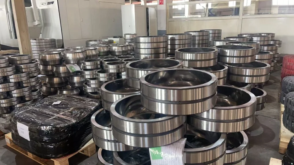
That division of labor creates specific maintenance requirements in the roll shop: matching inner rings for regrinding, checking under-roller diameter Fw before assuming cross-brand substitution, and choosing between solid comb brass cages and hollow-roller pin-type cages.
1. Comb Brass Cage (FC / FCD) vs Pin-Type Hollow Roller Cage (FCDP/YA3)
Within identical outer dimensions—such as the widely used 280 x 390 x 275 mm roll-neck envelope—engineers encounter both machined comb cages and pin-type cages:
- FC / FCD Machined Comb Brass Cage: Solid rollers sit in pockets of a rigid one-piece or split machined brass comb cage. It offers straightforward grease or oil flow and strong pocket stiffness under shock rolling passes.
- FCDP/YA3 Pin-Type Cage with Bored Rollers: Central steel pins pass coaxially through hollow-bored rollers and are anchored to side retaining rings. Eliminating thick inter-roller cage bridges lets the bearing pack larger roller diameters or extra rollers into the exact same radial space, raising dynamic radial capacity (
Cr).
- Solid rollers (confirm cage & groove layout on drawing)
- 280 x 390 x 275 mm | Cr = 2,260 kN | Cor = 6,940 kN
- Bored rollers on steel pins → higher dynamic rating
- Cr = 2,720 kN | Cor = 6,130 kN | Verify Fw before swapping
2. Catalogue Data Proof: Why Boundary Dimensions Alone Mislead Buyers
Consider two real entries from the ZQM technical catalogue that share the exact same 280 x 390 x 275 mm outer envelope and 105 kg mass:
| Catalogue Model | d x D x B/T | Fw (Under-Roller Dia.) | Dynamic Cr | Static Cor | r1,2min / r3,4min | Primary Reference |
|---|---|---|---|---|---|---|
| FCDP5678275/YA3 | 280 x 390 x 275 mm | 308 mm | 2,720 kN | 6,130 kN | 3.0 mm | Pin-type hollow-roller design |
FC5678275/YA3 |
280 x 390 x 275 mm | 312 mm | 2,260 kN | 6,940 kN | 3.0 mm | Alternate Fw & internal layout |
| FCD5678275 | 280 x 390 x 275 mm | 308 mm | 2,720 kN | 6,130 kN | 3.0 mm | Chock assembly ref (verify Fw & rings) |
Engineering warning: Notice the 4.0 mm difference in Fw between FCDP5678275/YA3 (Fw = 308 mm) and FC5678275/YA3 (Fw = 312 mm). Outer dimensions match, yet inner rings and roller assemblies are physically incompatible!
3. Roll-Neck Grinding and Matched Inner Rings in the Roll Shop
Because rolling mill work rolls are frequently pulled for roll-surface redressing, four-row cylindrical roller bearings allow the loose outer ring and roller assembly to stay inside the chock while the inner ring remains interference-fitted on the roll neck:
- Matched vs interchangeable inner rings: Keep serialized inner rings paired with their matched outer assemblies unless the bearing is explicitly ordered and manufactured for loose-set interchangeability with controlled
Fwradial clearance group. Mixing random spare inner rings across vendors shifts operating clearance unevenly across the four rows. - Final grinding on the roll neck: When a mill uses spare inner rings permanently shrunk onto multiple rolls, raceway OD (
Fw) is often finish-ground concentrically with the roll body to keep total radial runout within strip-gauge tolerances. - Thermal axial float: Because cylindrical raceways are flangeless on the floating side (or grouped as
FC/FCDsplit assemblies), axial elongation of a hot work roll slides cleanly across the raceway without preloading the chock.
4. Cross-Brand Identification (ISO Nominal Dimensions Disclaimer)
Mill maintenance teams often encounter legacy part markings such as SKF BC4-0100 (legacy 314719 C), FAG 527104, or NSK 280RV3903 alongside ZQM’s FCD5678275 or FCDP5678275/YA3. Always treat cross-brand numbers as nominal boundary identification references (280 x 390 x 275 mm), never automatic blind swaps. Before placing a purchase order, confirm:
- Exact
Fwraceway diameter (308 mmvs312 mm) and whether inner rings are one-piece, two-piece split, or ground-to-match; - Outer-ring lubrication groove and oil-hole positioning relative to chock feed ports;
- Radial internal clearance group (
C3/C4—confirm against shrink-fit interference and roll-neck temperature); - Separate axial locating capacity via a companion four-point contact ball bearing (116756 / QJF1058MB) or tapered thrust unit.
Send your rolling mill bearing designation, Fw requirement, and chock drawing to ZQM Bearings to verify internal layout, clearance, and lead time before releasing mill spares.
Frequently Asked Questions
1. Can a four-row cylindrical roller bearing carry axial rolling thrust?
No. Four-row cylindrical roller bearings support radial roll-separating forces only. They must be paired in the chock with a dedicated axial locating bearing—such as a QJF/QJ four-point contact ball bearing or double-direction thrust bearing—when roll designs generate axial loads.
2. Why are FCDP pin-type cages used on heavy roll necks?
By threading steel pins through bored hollow rollers instead of placing solid brass struts between rollers, pin-type cages pack higher roller load capacity into a severely restricted chock wall thickness.
3. Why did two 280x390x275 mm bearings fail to assemble when inner and outer halves were mixed?
Even with identical bore (280 mm), OD (390 mm), and width (275 mm), different series or manufacturers use different Fw raceway diameters (such as 308 mm vs 312 mm) and four-row split-ring layouts. Inner and outer assemblies must stay matched by serial or confirmed interchangeable on drawing.
4. Should FCD5678275 always be assumed to have C3 or C4 clearance?
Do not assume clearance from the base designation. Shrink fits on roll necks plus elevated hot-mill temperatures require specifying exact C3, C4, or special radial clearance on the purchase order.