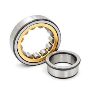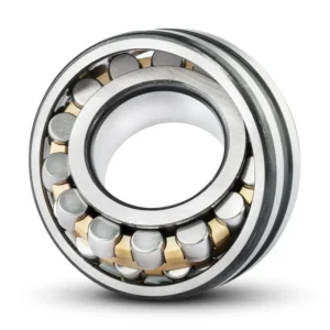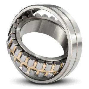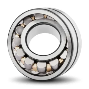

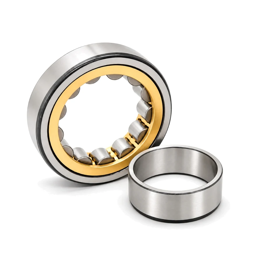
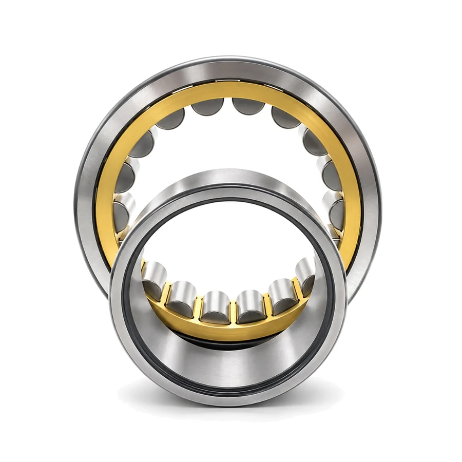
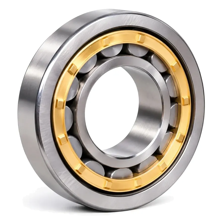
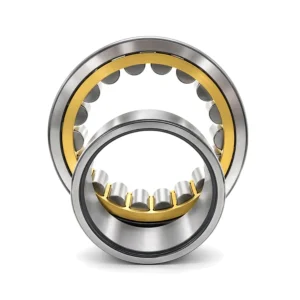
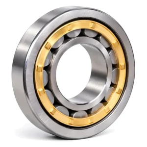
NU226EM Cylindrical Roller Bearing Overview
Built as a pure non-locating floating unit with two outer-ring ribs and a flangeless separable inner ring on a straight bore, NU226EM (130 × 230 × 40 mm, 7.90 kg) accommodates axial thermal shaft growth inside the roller raceway without binding. It delivers Cr = 345 kN, Cor = 425 kN, Fw = 153.5 mm, and speeds to 2,200 rpm grease / 2,800 rpm oil.
NU226EM Technical Specifications & Dimensions
| Parameter Category | Technical Parameter (Symbol) | Catalogue Reference Value |
|---|---|---|
| Boundary Dimensions & Weight | Bore diameter (d) | 130 mm |
| Boundary Dimensions & Weight | Outside diameter (D) | 230 mm |
| Boundary Dimensions & Weight | Width (B) | 40 mm |
| Boundary Dimensions & Weight | Roller set under-raceway diameter (Fw) | 153.5 mm |
| Boundary Dimensions & Weight | Reference mass (Weight) | 7.90 kg |
| Load Ratings & Limiting Speeds | Basic dynamic load rating (Cr) | 345 kN |
| Load Ratings & Limiting Speeds | Basic static load rating (Cor) | 425 kN |
| Load Ratings & Limiting Speeds | Limiting speed (grease) | 2200 rpm |
| Load Ratings & Limiting Speeds | Limiting speed (oil) | 2800 rpm |
| Abutment & Fillet Dimensions | Shaft abutment reference diameter (db) | 146 mm |
| Abutment & Fillet Dimensions | Housing abutment diameter (Da) | 212 mm |
| Abutment & Fillet Dimensions | Minimum chamfer dimension (r12) | 3 mm |
| Abutment & Fillet Dimensions | Minimum flange chamfer (r34) | 3 mm |
| Abutment & Fillet Dimensions | Maximum fillet radius (ra) | 2.5 mm |
| Abutment & Fillet Dimensions | Maximum flange fillet radius (rb) | 2.5 mm |
Data source: ZQM Bearings online catalogue database (factory PDF catalogue v1). Load ratings, limiting speeds, and parameters without individual test records serve as catalogue reference values; verify shaft/housing shoulders (da, db, Da), tolerances, internal clearance, and drawings prior to ordering.
Designation Breakdown & 130 mm Bore Selection
Key execution codes for NU226EM and engineering comparison across 130 mm bore catalogue alternatives:
| Attribute | Code / Option | Engineering Notes |
|---|---|---|
| NJ / NU & EM Execution | NU226EM |
Outer ring 2 ribs, flangeless inner ring (pure non-locating axial float); reinforced E rollers; machined brass cage (M); straight cylindrical bore |
| Internal Clearance | C0 (Normal) / C3 | Select C3 radial clearance when heavy shaft interference fits or 2,200+ rpm heat reduce operating play |
| Under-Roller Envelope | Fw = 153.5 mm | Straight-bore inner raceway allows separable mounting; Ew and Db/da: Contact us for specifications |
Compared with single-locating NJ226EM (Cr 290 kN, 7.38 kg), this floating design provides 19% higher dynamic capacity (Cr 345 kN) in the identical 130 × 230 × 40 mm space; NU326EM scales up to 280 × 58 mm for Cr 615 kN.
| Catalogue Unit | Envelope & Mass | Ratings & Grease Limit |
|---|---|---|
| NU226EM (Current) | 130 × 230 × 40 mm · 7.90 kg | Cr 345 kN · C0r 425 kN · 2,200 rpm |
| NJ226EM | 130 × 230 × 40 mm · 7.38 kg | Cr 290 kN · C0r 410 kN · 2,200 rpm |
| NU326EM | 130 × 280 × 58 mm · 19.3 kg | Cr 615 kN · C0r 735 kN · 1,800 rpm |
| NU2320M | 100 × 215 × 73 mm · 13.2 kg | Cr 440 kN · C0r 630 kN · 2,400 rpm |
Brand Cross-Reference & Interchangeability
Manufacturer designations sharing the 130 × 230 × 40 mm nominal ISO boundary envelope (full product catalog):
| Manufacturer | Reference Code | Verification Scope |
|---|---|---|
| ZQM Bearings | NU226EM |
Machined brass cage cylindrical unit per ISO 15 boundary dimensions |
| SKF | NU 226 ECM | Reinforced cylindrical design with machined brass cage |
| FAG / Schaeffler | NU226-E-XL-M1 | X-life cylindrical series with M1 solid brass cage |
| NSK | NU226EM | High-capacity cylindrical series with brass cage |
| NTN | NU226EG1 | Machined brass cage industrial execution |
Engineering Interchange Disclaimer: Cross-reference for identification only. Verify interchangeability with engineering drawings. Listed references share nominal ISO boundary dimensions (130 × 230 × 40 mm) only; internal geometry, cage execution, and load ratings vary by manufacturer.
Industrial Applications & Mounting Guidance (130 mm Shaft Class)
Primary machinery roles and field mounting practices matched to this 130 × 230 × 40 mm assembly:
| Target Machinery | Operating Duty Profile | Mounting & Lubrication Practice |
|---|---|---|
| Large Traction & Industrial Motor Floating Ends | Thermal rotor shaft expansion at 2,200–2,800 rpm with heavy radial pulley load | Allow internal axial float between rollers and flangeless inner ring rather than housing-bore sliding |
| Hot Process Fan & Centrifugal Compressor Drives | Rapid shaft-to-housing ΔT along long bearing spans | Separable straight-bore inner ring simplifies heated shaft mounting prior to casing closure |
| Industrial Spur & Helical Gearbox Output Float | Pure radial gear separation forces on non-locating end | Pair opposite a locating ball or paired-tapered unit to prevent axial preload lockup |
For reliable service life under ISO 281 fatigue calculations, maintain clean oil filtration, monitor housing temperature stabilization after initial run-in, and verify shaft journal roundness and shoulder squareness against the published abutment geometry before final press or sleeve installation. Post-mount feeler gauge measurements (on applicable radial structures) confirm mounted residual radial clearance—distinguishing it from final operating clearance under thermal equilibrium—while export batches include protective rust-inhibitor coating, individual VCI wrapping, and heavy-duty plywood crating tailored to sea or air transit.
Pre-Order Engineering Checklist
Confirm these three verification checkpoints with our engineering desk prior to scheduling factory dispatch for this 130 × 230 × 40 mm model:
| Checkpoint | Parameters to Confirm | Engineering Purpose |
|---|---|---|
| 1. Code & Clearance | Specify NU226EM, C0/C3/C4 play, and straight bore |
Aligns mounted internal play with shaft interference and running ΔT |
| 2. Shoulder & Fit Limits | Verify db 146 mm, Da 212 mm, ra 2.5 mm; Db/da: Contact us for specifications | Prevents chamfer interference and inner-ring creep |
| 3. Quantity & QC Scope | Unit mass 7.90 kg; state batch qty, EXW/FOB/CIF terms, and CMM/UT/hardness needs | Confirms pallet crating, MOQ lead time, and inspection records |
Frequently Asked Questions
What are the exact size, Fw, and weight of NU226EM?
Catalogue values list 130 mm straight cylindrical bore, 230 mm outside diameter, 40 mm width, under-roller diameter Fw = 153.5 mm, and 7.90 kg unit mass.
Why use a floating cylindrical design instead of sliding an outer ring in its housing?
Internal axial float on precision-ground rollers occurs with virtually zero friction under heavy radial load, eliminating housing fretting corrosion. For unquoted Db, da, or Ew values, Contact us for specifications.
Which shoulder and fillet dimensions apply to this 130 mm floating unit?
Catalogue specs show db min = 146 mm, Da max = 212 mm, chamfers r1,2/r3,4 min = 3 mm, and fillets ra/rb max = 2.5 mm; Contact us for specifications on unquoted Db and da dimensions.
How do axial float allowance, C3 clearance, and factory QC affect 130 mm floating orders?
When pairing floating units on hot 130 mm shafts, confirm both C3 radial play and allowable internal axial displacement versus rotor thermal growth. Reach out to ZQM for export crating, MOQ lead time, and CMM/hardness/UT inspection sheets.