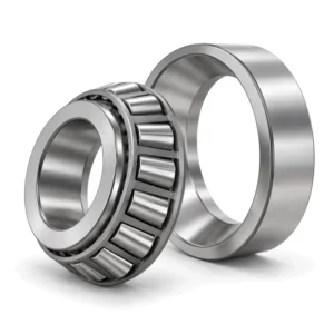

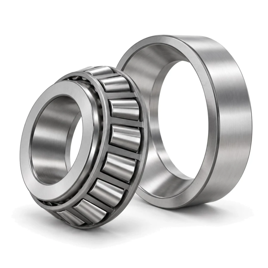
Descending a steep quarry haul road under a 100-ton payload hammers every rigid rear-axle spindle with combined vertical tire reactions and severe cornering side-thrust. Built to ISO 355 metric envelope dimensions of 130 × 230 × 67.75 mm (total assembly width T) with a 64 mm inner cone (B), 54 mm outer cup (C), and 11.0 kg mass, the ZQM 32226 tapered roller bearing delivers 495 kN dynamic radial capacity (Cr) and 740 kN static load resistance (C0r) inside mining haul-truck planetary wheel hubs and final-drive reduction units.
32226 Technical Specifications & Dimensions
| Parameter Category | Technical Parameter (Symbol) | Catalogue Reference Value |
|---|---|---|
| Boundary Dimensions & Weight | Bore diameter (d) | 130 mm |
| Boundary Dimensions & Weight | Outside diameter (D) | 230 mm |
| Boundary Dimensions & Weight | Inner-ring width (B) | 64 mm |
| Boundary Dimensions & Weight | Overall width (T) | 67.75 mm |
| Boundary Dimensions & Weight | Outer-ring width (C) | 54 mm |
| Boundary Dimensions & Weight | Reference mass (Weight) | 11 kg |
| Load Ratings & Limiting Speeds | Basic dynamic load rating (Cr) | 495 kN |
| Load Ratings & Limiting Speeds | Basic static load rating (Cor) | 740 kN |
| Abutment & Fillet Dimensions | Shaft abutment diameter (da) | 158 mm |
| Abutment & Fillet Dimensions | Shaft abutment reference diameter (db) | 141 mm |
| Abutment & Fillet Dimensions | Housing abutment diameter (Da) | 206 mm |
| Abutment & Fillet Dimensions | Housing abutment reference diameter (Db) | 222 mm |
| Abutment & Fillet Dimensions | Minimum chamfer dimension (r12) | 4 mm |
| Abutment & Fillet Dimensions | Minimum flange chamfer (r34) | 3 mm |
| Abutment & Fillet Dimensions | Maximum fillet radius (ra) | 3 mm |
| Abutment & Fillet Dimensions | Maximum flange fillet radius (rb) | 2.5 mm |
| Abutment & Fillet Dimensions | Load center distance (a) | 53.5 mm |
| Calculation Factors | Calculation factor (e) | 0.39 |
| Calculation Factors | Axial load factor (static) (Y0) | 0.85 |
| Calculation Factors | Axial load factor (Y) | 1.5 |
Data source: ZQM Bearings online catalogue database (factory PDF catalogue v1). Load ratings, limiting speeds, and parameters without individual test records serve as catalogue reference values; verify shaft/housing shoulders (da, db, Da), tolerances, internal clearance, and drawings prior to ordering.
Load-Path Geometry of the 32226 in Opposed DB Wheel Hubs
Unlike single-axis radial units, a tapered roller assembly converts radial weight into an induced axial reaction—which is why haul-truck wheel ends always mount two 32226 units face-to-back or back-to-back (DB) across the cast spindle:
- Wide Effective Spread via Load Center a = 53.5 mm: Orienting two 32226 bearings in a DB back-to-back arrangement shifts pressure cone apices outward along the spindle, maximizing overturning-moment leverage whenever dual off-road tires hit rutted berms.
- Balanced Axial-to-Radial Geometry (e = 0.39, Y = 1.5): When lateral turning forces cross the Fa/Fr > 0.39 boundary, the 1.5 axial calculation factor accurately governs combined equivalent bearing load across banked switchbacks.
- Separable Cup-and-Cone Servicing: Because the 54 mm outer cup presses cleanly into the ductile-iron wheel hub while the 64 mm cone-and-roller cage subassembly slides over the 130 mm cylindrical spindle journal, field mechanics inspect hub raceways without torch-cutting hubs.
- 740 kN Shock Reserve Against Rock Drops: Shovel-loading impacts into empty dump beds spike static contact stress abruptly; thick case-hardened raceways prevent permanent brinelling marks during loading cycles.
ISO 355 Nominal Footprint Cross-Reference for 32226
| Supplier | Catalog Designation | d (mm) | D (mm) | T / B / C (mm) | Wheel-End Supply Scope |
|---|---|---|---|---|---|
| ZQM | 32226 | 130 | 230 | 67.75 / 64 / 54 | ISO 355 metric single-row; matched DB sets on request |
| SKF | 32226 J2/Q | 130 | 230 | 67.75 / 64 / 54 | Stamped steel cage, optimized roller-end contact |
| FAG / Schaeffler | 32226-A | 130 | 230 | 67.75 / 64 / 54 | Metric DIN 720 / ISO 355 wheel-hub execution |
| Timken | 32226M | 130 | 230 | 67.75 / 64 / 54 | Case-carburized metric tapered assembly |
| NSK / NTN | HR32226J / 4T-32226 | 130 | 230 | 67.75 / 64 / 54 | High-capacity metric tapered roller series |
Interchange reminder: Designations listed above align on ISO 355 nominal boundary dimensions (130 × 230 × 67.75 mm) strictly for initial identification and do not imply unconditional cup-and-cone mixing between brands. Always install complete matched sets from one manufacturer and confirm sub-unit interchangeability against the axle OEM overhaul manual.
Spindle Fits, Abutments & Locknut Axial Setting Protocol
- Control Dimensional vs Form Tolerances Separately: Machine the 130 mm straight cylindrical spindle journal and 230 mm hub bore to the axle builder’s ISO 286-1 IT6 dimensional fit class (typically a snug cone fit on the stationary spindle and interference cup fit in the rotating hub), while independently verifying ISO 1101 cylindricity, circularity, and shoulder perpendicularity so the outer cup never distorts oval.
- Machine Proper Hub & Spindle Shoulders: Hold minimum spindle backing abutment at da = 158 mm and hub shoulder diameter at Da = 206 mm, keeping mating shaft and housing corner fillets strictly below the rmin = 4.0 mm ring chamfer to prevent cone face cocking.
- Set Axial End-Play or Preload by Locknut Shimming—Never a Feeler Gauge: Internal clearance in a tapered roller pair does not exist until installation. Tighten the spindle locknut or shim pack while rotating the hub to seat all rollers against the cone guide rib, then verify final axial end-play (or specified preload rolling torque) with a magnetic-base dial indicator. Never poke a radial feeler gauge between tapered rollers and cup raceways.
- Check Cup Seating After Initial Thermal Run-In: Confirm full back-face contact of both 54 mm cups against the hub shoulders using a thin shim check before pouring gear oil.
Planetary Final-Drive Oil Filtration & Failure Prevention
Haul-truck planetary hubs share heavily loaded SAE 85W-140 or synthetic ISO VG 320/460 EP gear oil with sun-and-planet gears. Metallic gear wear particles and mud creeping past duo-cone mechanical face seals rapidly pit tapered roller end-faces and rib contacts. Inspect magnetic hub drain plugs every 250–500 operating hours, verify duo-cone O-ring toric seating at every tire-end teardown, and drain oil hot to flush suspended iron sludge away from the lower 32226 cone.
Wheel-Hub Procurement Checklist & Technical Support
Before placing a fleet overhaul order for 32226 hub bearings, compile four workshop checks: (1) whether single assemblies or pre-ground DB matched pairs with spacer rings are required, (2) spindle journal wear measurement across the 130 mm seat, (3) target axial end-play or rolling-torque spec from the truck service manual, and (4) current gear-oil viscosity and seal condition. Submit your fleet bill of materials and delivery schedule directly via our ZQM heavy-axle quotation desk.
Engineering Links & Tools: Calculate combined wheel-hub fatigue hours in the ISO 281 Bearing Life Calculator, review full database specs at 32226 Catalog Sheet, explore related sizes in Tapered Roller Bearings, or see heavy haulage case notes in Mining & Crushing Industries.
Haul-Truck Planetary Hub 32226 Engineering Q&A
Why must a 32226 bearing pair be adjusted axially with a dial indicator instead of a radial feeler gauge?
A single-row tapered roller bearing has no fixed factory radial clearance because cone and cup are separable. Running clearance or preload is established solely by axial positioning of one bearing against its opposing partner via the spindle locknut or calibrated shims, verified through axial end-play or hub rolling torque.
Can I reuse an old 32226 outer cup in the wheel hub and install only a brand-new cone assembly?
No. Even within ISO 355 nominal boundaries, slight differences in raceway crowning, roller taper angle, and prior wear geometry cause severe edge loading when an aged cup is paired with a fresh cone. Replace both cup (C = 54 mm) and cone (B = 64 mm) as a unified 67.75 mm assembly.
What is the engineering meaning of a = 53.5 mm on the 32226 specification sheet?
Dimension a = 53.5 mm marks the effective load center distance from the back face of the outer cup to the point where roller contact normals intersect the shaft centerline. In a DB back-to-back wheel hub, this dimension increases the effective support span between inboard and outboard bearings, resisting tire cornering moments.
How do factors e = 0.39 and Y = 1.5 affect axle fatigue-life calculations?
When cornering thrust exceeds 39% of radial tire load (Fa/Fr > 0.39), the axial component enters the ISO 281 equivalent dynamic load formula multiplied by Y = 1.5, enabling accurate L10h forecasting for steep mine ramp grades.