

Single-row tapered roller assemblies carry combined radial and single-direction axial loads, which means every radial force generates an induced axial thrust (~0.5 × Fr / Y) that must be reacted by an opposing unit. Getting tapered roller bearing preload clearance right during gearbox or spindle assembly separates quiet, long-life shafts from early thermal seizure or chattering gear mesh.
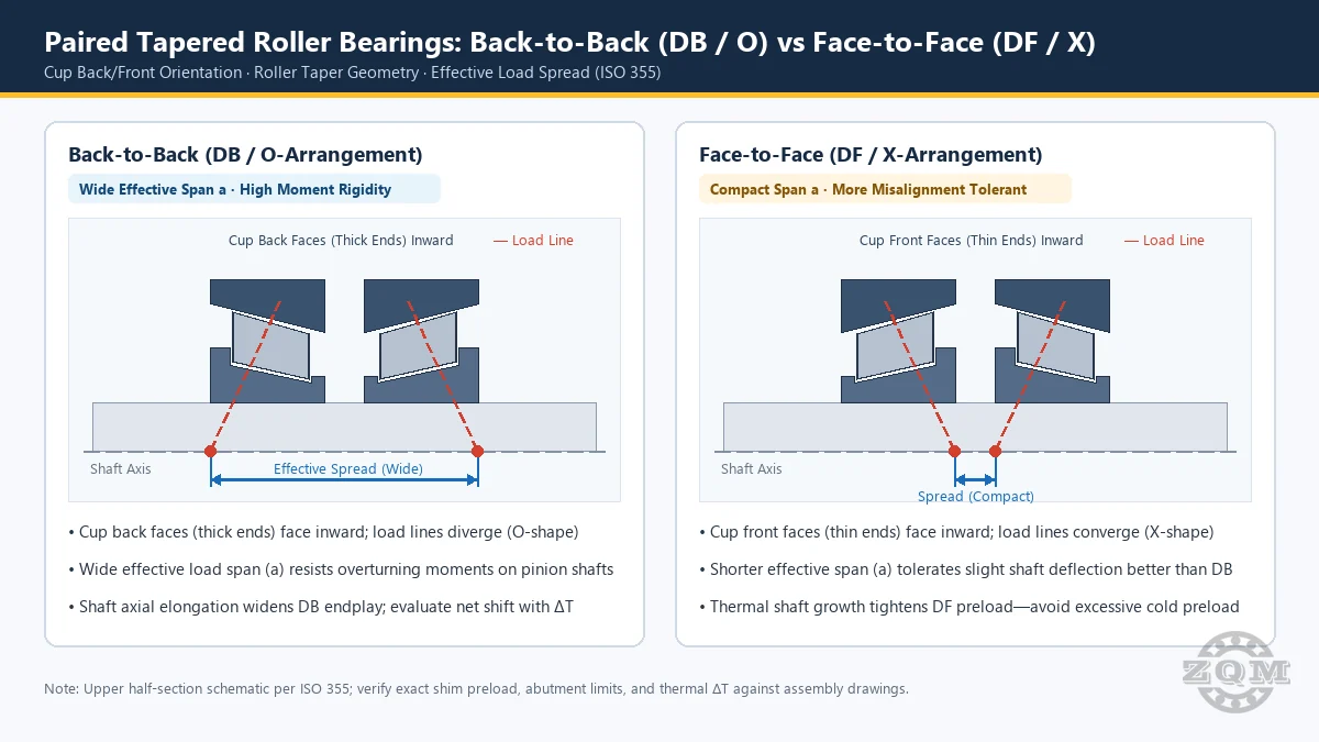
Preload vs Axial Endplay: DB (Back-to-Back) vs DF (Face-to-Face) Physics
Before dialing in shims or spacer widths for tapered roller bearing preload clearance, confirm whether the shaft uses a DB (back-to-back) or DF (face-to-face) arrangement—because shaft heating shifts axial clearance in opposite directions:
- Effective load centers
aproject outward, creating a wide support span that resists overturning moments. - When the steel shaft runs hotter than the cast-iron housing, axial shaft elongation tends to widen DB axial endplay (whereas inner-ring radial expansion acts in the opposite direction—evaluate net clearance shift by bearing span and ΔT).
- Effective load centers converge inward, offering slightly better tolerance to static housing misalignment.
- When the shaft heats up faster than the housing, axial shaft expansion tightens preload—setting negative clearance too tight risks rapid thermal runaway!
Note a critical engineering rule: tapered rollers have tapered raceways, NOT a tapered bore. Every standard single-row tapered unit in the ZQM catalog—including 32220, 32224, 32324, and 322 series units—uses a straight cylindrical bore.
Verified Dimensions & Load Centers: 302, 320X, 322, 323 & 331 Series
Accurate axial spacer machining requires exact total width T, cone width B, cup width C, and effective load center a conforming to ISO 15 / ISO 355 boundary plans. The table below compiles verified ZQM database parameters for 100 mm and 120 mm bore shafts:
| Designation (Straight Bore) | d × D × T (B / C) & Load Center a | Ratings (Cr / Cor), Factors & Mass |
|---|---|---|
| 32020X (Medium-light compact section) | 100 × 150 × 32 mm (B=32, C=24, a=32.5 mm) | Cr 176 kN / Cor 294 kN · e=0.46, Y=1.3, Y0=0.72 · 1.95 kg |
| 33120 (Compact heavy section; see catalog 33120) | 100 × 165 × 52 mm (B=52, C=40, a=40.1 mm) | Cr 325 kN / Cor 523 kN · e=0.41, Y=1.48, Y0=0.81 · 4.29 kg |
| 30220 (Standard light-medium section) | 100 × 180 × 37 mm (B=34, C=29, a=36.1 mm) | Cr 255 kN / Cor 330 kN · e=0.42, Y=1.4, Y0=0.79 · 3.78 kg |
| 32220 (Wide medium section) | 100 × 180 × 49 mm (B=46, C=39, a=41.5 mm) | Cr 325 kN / Cor 450 kN · e=0.42, Y=1.4, Y0=0.79 · 5.05 kg |
| 32320 (Steep heavy shock section) | 100 × 215 × 77.5 mm (B=73, C=60, a=53.2 mm) | Cr 565 kN / Cor 755 kN · e=0.35, Y=1.7, Y0=0.96 · 12.7 kg |
| 32224 (120 mm gearbox standard) | 120 × 215 × 61.5 mm (B=58, C=50, a=52 mm) | Cr 440 kN / Cor 635 kN · e=0.44, Y=1.4, Y0=0.76 · 9 kg |
| 32324 (120 mm extreme thrust & shock) | 120 × 260 × 90.5 mm (B=86, C=69, a=62.4 mm) | Cr 770 kN / Cor 1,060 kN · e=0.35, Y=1.7, Y0=0.96 · 21.8 kg |
Note on limiting speeds: in the ZQM database, grease and oil limiting speeds for 30220, 32220, 32320, 32020X, 33120, 32224, and 32324 are unspecified (Contact us for specifications)—never estimate speed limits when sizing oil-bath vs splash-lubricated pinions. On 33120, shaft abutment db is also unspecified (Contact us for specifications; verified abutments are da >= 112 mm, Da <= 142 mm, Db >= 159 mm).
Shop-Floor Setting Workflow: Shims, Spacers & Rolling Torque
Achieving repeatable tapered roller bearing preload clearance requires measuring mechanical reality after full shaft clamping rather than relying solely on locknut torque:
- Seat Rollers Before Measuring: Press cups squarely against housing shoulders (
Db >= 208 mmon 32224;Db >= 248 mmon 32324). Spin the shaft 10–15 turns under light axial load so roller large ends seat cleanly against the inner-ring guide rib. - Measure Axial Endplay or Rotational Drag Torque: For positive axial clearance (typical heavy industrial gearboxes), tighten the end-cap bolts without shims until zero play, measure the feeler gap, and insert a shim pack equal to gap plus target endplay. For preloaded pinion shafts, tighten the locknut or grind the spacer until rotational breakaway and running torque hit the gearbox specification.
- Account for Aluminum vs Steel Housing Thermal Growth: When a steel shaft runs inside an aluminum housing, the housing expands roughly twice as fast axially and radially, opening DF clearance at operating temperature—verify cold tapered roller bearing preload clearance against steady-state ΔT.
Frequently Asked Questions
When should a gearbox shaft use preload versus positive axial clearance?
Specify light preload on precision bevel pinions, machine-tool spindles, and stiff helical shafts where gear tooth contact pattern stability is critical. Specify positive axial endplay on heavily loaded quarry conveyors, mill drives, and splash-lubricated gearboxes exposed to wide shaft-to-housing temperature swings.
How do 320X and 331 series compare with 302 and 322 at 100 mm bore?
At d = 100 mm, 32020X offers a low 150 mm OD and 32 mm width (Cr 176 kN) for tight radial envelopes, whereas 33120 (165 mm OD, 52 mm width) matches the 325 kN dynamic rating of wider 32220 (180 mm OD, 49 mm width) inside a 15 mm smaller housing bore.
Why does DF mounting tighten preload as the shaft heats up?
In a DF (face-to-face) arrangement, the inner rings sit between the cups and expand axially outward along the hotter shaft toward the cooler housing cups, closing internal play and increasing preload—making accurate thermal ΔT allowance mandatory.
Related ZQM Engineering Tools & Product Hub
- ISO 281 Bearing Life Calculator — evaluate combined radial + axial load
PandL10hfor 302 / 320X / 322 / 323 / 331 tapered roller presets (including32226). - Tapered Roller Bearings Category Hub — inspect full ISO 355 dimension tables and ZQM catalog stock models.
- Angular Contact 70/72/73 DB/DF/DT Pairing Guide — compare face-to-face and back-to-back shaft stiffness principles on high-speed pump and gearbox shafts.
Sourcing 302, 320X, 322, 323, or 331 Tapered Roller Sets?
Share your shaft diameter, DB/DF spacing, and target preload or endplay range. ZQM engineers confirm cone/cup width tolerances (T, B, C), abutment shoulders, and factory speed ratings for your application.