

Single-row angular contact ball bearings in the 70, 72, and 73 series carry combined radial and axial loads across API 610 multistage centrifugal pumps, rotary screw compressors, vertical chemical agitators, and high-speed industrial gearboxes. Because a single-row bearing can support axial thrust in one direction only, industrial shafts almost always mount them in matched pairs—Back-to-Back (DB), Face-to-Face (DF), or Tandem (DT)—and pair the right contact angle (25° AC vs 40° B) with a machined solid brass cage (M). Choosing the wrong contact angle or clamping unmatched single-row rings together is one of the fastest paths to bearing seizure on commissioning.
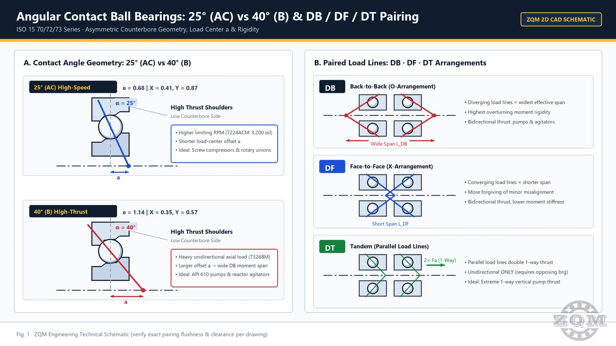
1. Contact Angle Physics: 25° (AC) vs 40° (B) Under ISO 281
In an angular contact ball bearing, the nominal contact angle α is the angle between the line joining the ball-to-raceway contact points and a plane perpendicular to the shaft axis. Increasing α from 25° (AC) to 40° (B) fundamentally changes how radial force Fr and axial thrust Fa combine into the ISO 281 equivalent dynamic bearing load P = X·Fr + Y·Fa (for single-row operation when Fa / Fr > e):
- Higher radial dynamic capacity and shorter load-center distance
awithin the same boundary envelope. - Lower ball spin-to-roll ratio reduces contact heat, supporting higher limiting speeds in high-speed spindles, blower drives, and precision pump shafts.
- Best fit when radial load dominates or axial thrust is moderate relative to shaft speed.
- Much smaller axial factor
Y = 0.57dramatically lowers equivalent loadPunder severe axial thrust. - Longer load-center distance
awidens the effective moment span when mounted back-to-back (DB). - Standard choice for API 610 process pumps, discharge ends of rotary screw compressors, and vertical agitator thrust stacks.
Notice the direct design proof inside the exact same 100 × 180 × 34 mm envelope: 7220ACM (25°) delivers higher radial dynamic rating (Cr = 114 kN, C0r = 130 kN) with e = 0.68 and Y = 0.87, whereas 7220BM (40°) trades part of its pure radial rating (Cr = 100 kN, C0r = 114 kN) to cut the axial multiplier down to Y = 0.57 (e = 1.14). Once Fa / Fr climbs above 1.14 on a heavy process pump or screw-compressor discharge rotor, the 40° B bearing achieves a substantially lower equivalent load P and longer calculated fatigue life. You can evaluate your exact radial-to-axial load ratio and speed before finalizing a series using our ISO 281 Bearing Life Calculator.
2. Verified ZQM Catalog Comparison: 70 / 72 / 73 BM and ACM Series
The reference table below compiles verified dimensions, load ratings, mass, limiting speeds, and load-center distances a from our angular contact ball bearing catalog across bores from 100 mm to 140 mm:
| Model | d × D × B (mm) | Contact Angle | Ratings Cr / C0r (kN) | Mass (kg) | Verified Engineering Parameters |
|---|---|---|---|---|---|
| 7220BM | 100 × 180 × 34 | 40° (B) | 100 / 114 | 4.00 | e = 1.14 · Y = 0.57 |
| 7220ACM | 100 × 180 × 34 | 25° (AC) | 114 / 130 | 3.74 | e = 0.68 · Y = 0.87 |
| 7224ACM | 120 × 215 × 40 | 25° (AC) | 146 / 184 | 6.04 | 2,200 / 3,200 rpm · a = 59.1 mm |
| 7226BM | 130 × 230 × 40 | 40° (B) | 135 / 175 | 7.56 | 1,900 / 2,800 rpm · a = 95.5 mm |
| 7326BM | 130 × 280 × 58 | 40° (B) | 251 / 270 | 17.5 | 1,800 / 2,600 rpm · a = 115.0 mm |
| 7028ACM | 140 × 210 × 33 | 25° (AC) | 98 / 137 | 4.14 | 2,000 / 3,000 rpm · a = 57.3 mm |
Compare the cross-section and load-center shifts across the table. Stepping from the medium 72 series (7226BM, 130 × 230 × 40 mm, Cr 135 kN, a = 95.5 mm) to the heavy 73 series (7326BM, 130 × 280 × 58 mm, Cr 251 kN, a = 115.0 mm) nearly doubles dynamic load capacity on the same 130 mm shaft while expanding the back-to-back load-center spread. Meanwhile, compact-section light series units like 7028ACM (140 × 210 × 33 mm, 4.14 kg, a = 57.3 mm), 7022ACM, and 7024ACM fit tight radial envelopes at higher speeds, while intermediate industrial shafts commonly rely on 7320BM, 7222BM, 7322BM, and 7324BM.
3. Paired Mounting Engineering: DB vs DF vs DT
Because an angular contact ball bearing produces an induced internal axial force even under pure radial loading, industrial shafts use matched pairs to establish axial location, control stiffness, and share thrust loads cleanly. Each pairing geometry alters effective load-center spacing, moment rigidity, and thermal behavior:
| Arrangement | Load-Line Geometry | Axial Thrust Direction | Moment Stiffness and Alignment | Primary Industrial Equipment |
|---|---|---|---|---|
| DB (Back-to-Back) | Diverging toward shaft axis (<>); widest effective span 2a outward |
Bidirectional (locates shaft in both axial directions) | Highest overturning moment stiffness; sensitive to severe shaft/housing misalignment | API 610 overhung process pumps, vertical chemical agitators, screw compressor discharge ends, bevel-pinion shafts |
| DF (Face-to-Face) | Converging toward shaft axis (><); narrow effective span inward |
Bidirectional (locates shaft in both axial directions) | Lower moment stiffness, but slightly more forgiving of minor housing-bore misalignment | Compact gearboxes with separate radial support, short-span housings with lower bore coaxiality |
| DT (Tandem) | Parallel load lines (<<); both rows share thrust equally when matched |
Unidirectional only (must be opposed by a second locating bearing) | Doubles thrust capacity in one direction; requires opposing bearing to prevent axial unloading | High-pressure vertical turbine pumps, heavy screw-compressor rotors, high-thrust extruder shafts (often in DB+DT triplex sets) |
Thermal Expansion Caution on DB vs DF Pairs
In a DB pair, inner-ring faces are clamped together by the shaft locknut while the outer rings seat inside the housing bore. If the shaft runs significantly hotter than a water-cooled or ambient-air-cooled housing, axial thermal growth of the shaft plus radial inner-ring expansion can gradually tighten internal preload in a DB pair—especially on high-speed 40° B compressors. Conversely, in a DF pair, radial expansion of the inner rings also reduces clearance, so designers must calculate shaft interference expansion and inner-to-outer ring temperature differentials before choosing between light axial clearance (e.g., CA / CB) and light preload (GA) executions.
4. Machined Solid Brass Cage (M) and the Unground Pairing Trap
Every model in our heavy 70/72/73 BM and ACM range uses a one-piece machined solid brass cage (M). In industrial rotating equipment, cage survival often determines real-world reliability well before raceway fatigue occurs:
- Screw Compressors and Gas Blowers: High discharge oil temperatures, rapid pressure pulsations, and synthetic polyglycol or ester lubricants can embrittle glass-reinforced polyamide cages over time. Solid machined brass cages hold pocket geometry cleanly across high continuous operating temperatures and transient pressure spikes.
- API 610 Multistage Centrifugal Pumps: Flow recirculation, off-BEP cavitation vibration, and momentary thrust reversals subject cages to sharp acceleration loads. A solid brass cage guided on the balls or ring shoulders resists pocket cracking and debris generation.
- Vertical Chemical Agitators: Long cantilevered shafts impose oscillating bending moments and slow-speed start-stop cycles under thick slurry loads, where rigid machined brass guidance prevents ball bunching.
Warning: Never Pair Random Off-the-Shelf Unground Single-Row Bearings
One of the costliest field mistakes during urgent pump or compressor overhauls is buying two standard single-row bearings off the shelf—such as two unground 7220BM or 7326BM units—and clamping them back-to-back under a shaft locknut. Standard single-row bearings are not ground to controlled face stick-out tolerances. Depending on random manufacturing stack-up between the inner and outer ring widths, tightening the nut either:
- Over-preloads both rows immediately, spiking friction torque and oil temperature within minutes of startup until thermal runaway seizes the shaft; or
- Leaves excessive axial endplay, allowing the unloaded row to skid at high speed and hammer against the raceway shoulder during pump thrust reversals.
Always specify either factory-matched sets (DB, DF, or DT) supplied with matched serial numbers and a V-mark across the outer rings to verify assembly orientation, or universally matchable flush-ground bearings engineered to be paired in any DB, DF, or DT arrangement with a predictable axial clearance or preload class.
5. Pre-Order Engineering Checklist for Industrial Buyers
Before issuing a purchase order for paired 70/72/73 BM or ACM angular contact ball bearings, confirm these six technical points with your maintenance or rotating-equipment engineer:
- Full Designation and Contact Angle: Confirm whether the equipment drawing requires
40° (B)(e.g., 7222BM, 7324BM, 7326BM) or25° (AC)(e.g., 7024ACM, 7224ACM, 7028ACM). Never substitute25°for40°on a heavy-thrust pump without recalculatingL10h. - Pairing Execution (Factory Set vs Universal Ground): State explicitly whether you require a serialized
DB,DF, orDTmatched set or universally matchable flush-ground single bearings. - Mounted Axial Clearance or Preload Class: Specify light axial clearance (preferred for hotter pump and compressor shafts with interference fits) or defined light/medium preload (for rigid precision positioning).
- Shaft and Housing Fit + Thermal Delta: Provide shaft journal tolerance (typically
k5/m5depending on load), housing bore fit (H6/J6), and expected shaft-to-housing temperature difference so internal clearance loss is checked prior to supply. - Lubrication Method and Speed Regime: Confirm oil-bath, oil-mist, circulating oil-jet, or grease lubrication and operating speed against the bearing’s limiting speed.
- Order-Matched Inspection Scope: Review required dimensional, runout, clearance/stick-out, and laser-marking verification against our quality inspection and metrology workflow prior to shipment.
Frequently Asked Questions
When should engineers choose a 40° (B) angular contact ball bearing over a 25° (AC) model?
Choose a 40° (B) design such as 7220BM, 7226BM, or 7326BM when axial thrust dominates the duty cycle—such as API 610 multistage centrifugal pumps, discharge ends of oil-flooded screw compressors, and vertical chemical agitators. Under ISO 281, a 40° contact angle raises the axial threshold factor to e = 1.14 and lowers the axial load factor to Y = 0.57 (versus e = 0.68 and Y = 0.87 for 25° AC), reducing the equivalent dynamic load P under heavy axial thrust. Choose 25° (AC) models such as 7220ACM, 7224ACM, or 7028ACM when radial load is substantial, higher limiting speeds are required, or lower spin friction and heat generation are prioritized.
Why is back-to-back (DB) pairing preferred over face-to-face (DF) on overhung pumps and agitators?
In a back-to-back (DB) arrangement, the contact load lines diverge toward the shaft centerline, creating a much wider effective distance between load centers than a face-to-face (DF) pair of the same bearing size. That wider moment arm gives DB pairs significantly higher overturning moment stiffness against cantilevered impeller or agitator shaft bending. Face-to-face (DF) arrangements have a narrower effective span and lower moment rigidity, so they are mainly selected where slight housing bore misalignment must be tolerated and moment loads are modest.
Can a tandem (DT) pair of angular contact ball bearings locate a shaft in both axial directions?
No. A tandem (DT) arrangement aligns both contact load lines in parallel to share heavy unidirectional axial thrust across two bearings, effectively doubling axial capacity in one direction when factory-matched. However, a DT set cannot restrain reverse thrust or prevent axial unloading during startup and shutdown—it must always be opposed by a second locating bearing or an opposing angular contact bearing arranged in a back-to-back or face-to-face configuration against the tandem pair.
Can I pair two standard off-the-shelf single-row 7220BM or 7326BM bearings directly in DB or DF?
No—never clamp two unground standard single-row angular contact bearings together without verifying face flushness and ring offset. Standard single-row bearings are not ground with controlled face stick-out for adjacent mounting. Tightening a locknut across unmatched faces produces either unpredictable excessive preload—triggering rapid overheating and raceway smearing—or uncontrolled axial clearance that allows ball skidding and hammering on thrust reversal. Always specify either a factory-matched paired set (DB, DF, or DT) with a defined clearance or preload class, or universally matchable flush-ground single bearings.
Why do industrial 70/72/73 BM and ACM bearings use a machined solid brass cage (M) instead of polyamide?
A machined solid brass cage (M) maintains dimensional stability at elevated sump oil temperatures, resists chemical degradation from synthetic compressor lubricants and process-adjacent vapours, and withstands high centrifugal forces and pulsating discharge shocks in rotary screw compressors and heavy centrifugal pumps. Unlike stamped steel or glass-fiber polyamide cages, solid brass cages also provide rigid ball pocket guidance during rapid start-stop reversals and brief boundary-lubrication transients.
Specifying Paired 70 / 72 / 73 BM or ACM Angular Contact Bearings?
Share your bearing designation, contact angle (25° AC or 40° B), required DB/DF/DT arrangement, axial clearance or preload class, and pump or compressor operating conditions. ZQM engineers verify matched face geometry and inspection records before quoting.