

Heavy CNC gantry milling machines, floor-type boring mills, and large vertical turning lathes rely on double-row cylindrical roller spindle bearings (NN30 and NNU49 series) at the spindle nose to deliver maximum radial cutting rigidity inside a compact housing. Mastering NN30 1:12 tapered bore (K) radial clearance adjustment is the decisive skill separating chatter-free heavy roughing from thermal spindle seizure.
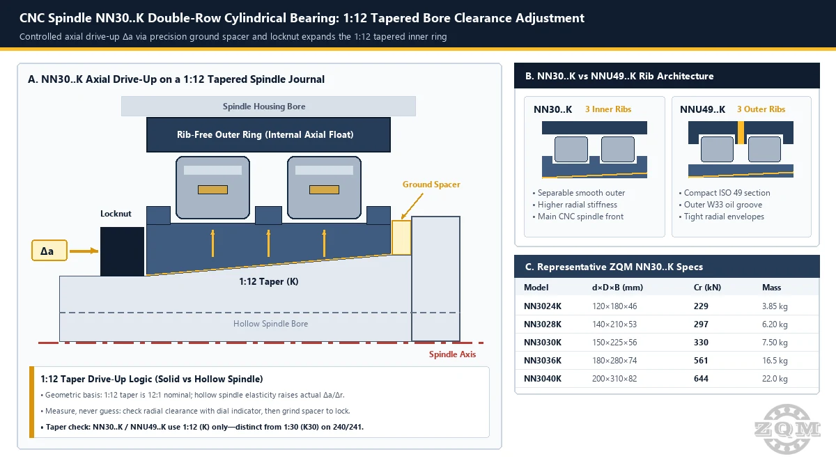
NN30..K vs NNU49..K: Rib Architecture and Pure Radial Duty
Before selecting or rebuilding a heavy-duty precision machine tool main spindle, verify which double-row cylindrical architecture matches the housing envelope and lubrication feed:
- Three integral ribs on the inner ring retain both roller rows; outer ring slides cleanly into the housing bore.
- Standard choice on CNC gantry milling, floor-type boring, and heavy lathe main spindle fronts.
- Lower radial section height maximizes spindle shaft diameter inside tight quills and grinding heads.
- Outer ring carries three ribs plus circumferential lubrication groove and radial oil holes (W33 layout).
Critical Engineering Boundary: Both NN30 and NNU49 accommodate axial shaft thermal displacement internally and carry radial loads only. Every CNC spindle must pair them with dedicated axial thrust bearings—typically bidirectional angular-contact thrust ball bearings or opposed tapered roller sets—to absorb axial feed and cutting thrust.
1:12 (K) Taper Drive-Up Physics: Solid vs Hollow Spindles
All standard tapered-bore NN30..K and NNU49..K bearings use a 1:12 taper (K)—never confuse them with the 1:30 (K30) taper used on wide-section 240 and 241 spherical roller bearings (see our 1:12 K vs 1:30 K30 Tapered Bore Guide).
On an ideally rigid solid shaft, advancing the inner ring axially by Δa along a 1:12 taper expands the bore diameter by Δa / 12. In real machine-tool spindles, two elastic realities alter that ratio:
- Hollow Spindle Elastic Contraction: CNC spindles are bored hollow to house drawbars and through-spindle coolant tubes. As the locknut pushes the inner ring up the taper, radial contact pressure slightly compresses the hollow shaft inward, reducing inner-ring raceway expansion efficiency. Consequently, actual axial drive-up per micron of radial clearance reduction is higher than
12:1—often13:1to15:1or greater depending on wall thickness. - Housing Bore Interference Contraction: Press-fitting the outer ring into the cast-iron or steel spindle housing contracts the outer raceway slightly, consuming a portion of unmounted radial clearance before the inner ring is even driven up.
For these reasons, seasoned spindle rebuilders never tighten an NN30..K locknut by torque wrench feel or nominal 12:1 math alone—always measure actual mounted radial clearance directly on the spindle.
Verified ZQM Catalogue Specifications: NN30..K and NNU49..K (120–200 mm Bore)
The table below summarizes verified boundary dimensions (ISO 15), dynamic/static load ratings, masses, and catalogue speed ratings for heavy-duty NN30..K and NNU49..K spindle sizes. Precision tolerance classes (ISO 492, such as P5 / P4 / SP per customer specification) and matched preload ranges are confirmed strictly against your spindle drawing before manufacture:
| Designation (1:12 K Taper) | d × D × B (mm) | Cr / C0r (kN) | Mass & Catalogue Speed |
|---|---|---|---|
| NN3024K | 120 × 180 × 46 | 229 / 390 | 3.85 kg · 5,000 r/min |
| NN3026K | 130 × 200 × 52 | 284 / 475 | 5.75 kg · 4,500 r/min |
| NN3028K | 140 × 210 × 53 | 297 / 520 | 6.20 kg · 4,300 r/min |
| NN3030K | 150 × 225 × 56 | 330 / 570 | 7.50 kg · 4,000 r/min |
| NN3032K | 160 × 240 × 60 | 369 / 655 | 9.10 kg · 3,800 r/min |
| NN3036K | 180 × 280 × 74 | 561 / 1,000 | 16.5 kg · 3,200 r/min |
| NN3040K | 200 × 310 × 82 | 644 / 1,140 | 22.0 kg · 2,000 r/min |
| NNU4924K | 120 × 165 × 45 | 176 / 340 | 2.80 kg · 5,300 r/min |
| NNU4932K | 160 × 220 × 60 | 330 / 680 | 6.60 kg · 4,000 r/min |
| NNU4940K | 200 × 280 × 80 | 484 / 1,040 | 15.0 kg · 3,000 r/min |
Browse all 78+ sizes in our NN30 Series Online Catalogue (straight-bore NN30 and NNU49 models share the exact boundary dimensions listed above).
Shop-Floor 5-Step Clearance Setting and Spacer Grinding Procedure
- Inspect Spindle Taper Contact and Housing Bore: Before mounting, blue-check the spindle
1:12journal against a master ring gauge (or the bearing inner ring) to verify uniform taper contact without high spots near the large or small end. Confirm housing bore cylindricity and shoulder squareness. - Mount Outer Ring and Measure Installed Envelopes: Seat the rib-free outer ring squarely in the spindle housing (applying even axial pressure on the outer face only). Record the actual mounted outer-ring raceway diameter using a precision bore gauge.
- Trial Drive-Up with Precision Locknut and Dial Indicator: Assemble the inner ring and roller assembly onto the tapered journal without the final spacer (or with an oversize trial spacer). Tighten the locknut incrementally while rotating the spindle and checking radial lift with a calibrated 0.001 mm dial indicator—stop as soon as radial clearance reaches the OEM drawing target (typically near zero or light radial preload depending on speed and lubrication).
- Measure Gap and Surface-Grind the Hardened Spacer Ring: Measure the exact axial distance between the inner-ring large end face and the spindle shoulder at multiple circumferential points, then finish-grind the hardened spacer ring to match (maintaining tight face parallelism per spindle drawing).
- Final Assembly, Lubrication and Step-Speed Run-In: Reassemble with the finish-ground spacer, tighten the precision locknut against the positive stop, apply clean metered grease or oil-air lubrication, and run a stepped speed-up profile while monitoring bearing-housing temperature stabilization to confirm preload is not excessive.
For paired tapered roller worktable and bevel-drive adjustment on vertical turning lathes, see our Tapered Roller Bearing Preload and Axial Clearance Guide and Heavy-Duty Precision Machine Tool Bearings.
Frequently Asked Questions
Why do CNC machine tool spindles use 1:12 tapered bore NN30..K bearings instead of straight-bore NN30?
A 1:12 tapered bore (K) allows spindle technicians to push the inner ring axially up the matching 1:12 tapered spindle journal, expanding the inner raceway radially by controlled microns until mounted radial clearance reaches zero or light radial preload. Straight-bore NN30 bearings rely purely on fixed shaft interference tolerances and cannot be finely dialed in during spindle rebuilds.
Does an axial drive-up of 12 microns on an NN30..K bearing always reduce radial clearance by exactly 1 micron?
No—12:1 is only the ideal rigid-shaft geometric ratio. Most heavy CNC milling and boring spindles have hollow tool-clamping bores that contract elastically under inner-ring radial pressure, meaning actual axial drive-up per micron of radial clearance reduction is typically higher than 12:1 (often around 13:1 to 15:1 or more depending on hollow-spindle wall ratio). Always verify radial clearance directly with a dial indicator.
What is the difference between NN30..K and NNU49..K double-row cylindrical spindle bearings?
NN30..K bearings have three integral ribs on the inner ring and a separable rib-free outer ring, giving higher cross-sectional stiffness for heavy CNC gantry and boring main spindles. NNU49..K bearings use the ultra-compact ISO 49 section with three ribs plus outer-ring lubrication grooves/holes on the outer ring and a separable rib-free inner ring, suited to tightly constrained radial envelopes. Both use a 1:12 (K) taper and carry radial loads only.
How is the final axial position of an NN30..K inner ring locked after clearance adjustment?
During trial assembly, use the spindle locknut to drive the inner ring up the 1:12 taper until the dial indicator confirms target zero clearance or light preload, measure the exact axial gap between the inner-ring large end face and the spindle shoulder, and finish-grind a hardened spacer ring to that measured thickness so tightening the locknut permanently locks the clearance without creep.
Sourcing NN30..K or NNU49..K Spindle Bearings to Drawing?
Share your spindle bearing designation, required ISO 492 tolerance class, radial clearance group, and lubrication layout. ZQM engineering verifies 1:12 taper requirements, drawing capability, and production lead times before quoting.