

In hot strip mills, cold reversing mills, and aluminum rolling plants, work-roll and backup-roll changes happen on tight schedules. To minimize mill downtime, maintenance teams leave the straight-bore inner rings interference-fitted on spare roll necks while outer-ring and roller assemblies circulate inside the chocks. That separable workflow makes four-row rolling mill bearing Fw verification and radial internal clearance control the two most critical checks preventing premature mill-stand seizure or spalling.
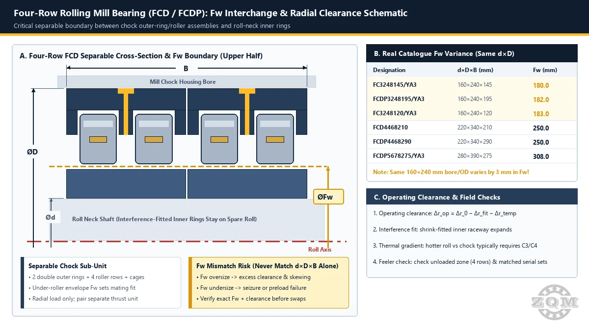
Why Nominal d × D × B Alone Fails on Separable Four-Row Roll-Neck Bearings
Unlike non-separable spherical roller bearings, a four-row cylindrical roll-neck bearing splits cleanly along the under-roller envelope diameter Fw—the inscribed circle diameter tangent to the inside surface of all four roller rows when seated against the outer-ring raceways. During roll changes, if an outer-ring/roller chock sub-unit from one bearing lot or brand is slid onto a spare roll carrying an inner ring with a different raceway diameter, the mismatch occurs right at Fw:
- Two double-width outer rings with integral guide ribs and outer-ring lubrication grooves/holes guide all four roller rows.
- Carries radial roll separating force only—the mill chock must house a separate axial locating thrust bearing.
- Shrink-fitted onto the roll neck to prevent inner-ring creep under extreme cyclic radial load.
- Interference expands the inner-ring raceway OD outward, directly reducing mounted radial clearance Δr.
Even within a single manufacturer’s catalogue, identical nominal bore d and outer diameter D do not guarantee identical Fw. In our steel and rolling mill bearing engineering reviews, mixed-brand chock swaps without confirming Fw are a leading root cause of immediate raceway smearing on startup.
Verified Catalogue Proof: Real Fw Differences Across 160–280 mm Bores
The table below compiles verified ZQM catalogue parameters for representative four-row FC, FCD, and FCDP rolling mill bearings. Notice how three 160 × 240 mm units vary by up to 3.0 mm in Fw, and how 280 × 390 × 275 mm models carry distinct Fw values depending on internal roller geometry:
| Designation (Straight Bore) | d × D × B (mm) | Fw (mm) | Ratings Cr / C0r (kN) & Mass |
|---|---|---|---|
| FC3248145/YA3 | 160 × 240 × 145 | 180.0 | Cr 920 / C0r 1,600 kN · 23.0 kg |
| FCDP3248195/YA3 | 160 × 240 × 195 | 182.0 | Cr 1,340 / C0r 2,600 kN · 33.0 kg |
| FC3248120/YA3 | 160 × 240 × 120 | 183.0 | Cr 745 / C0r 1,320 kN · 18.6 kg |
| FC3446180 | 170 × 230 × 180 | 186.0 | Cr 1,040 / C0r 2,690 kN · 24.5 kg |
| FC3446130 | 170 × 230 × 130 | 188.5 | Cr 780 / C0r 1,680 kN · 15.6 kg |
| FCD4468210 | 220 × 340 × 210 | 250.0 | Cr 1,910 / C0r 3,850 kN · 70.5 kg |
| FCDP4468290 | 220 × 340 × 290 | 250.0 | Cr 2,980 / C0r 5,010 kN · 96.5 kg |
| FCD5678275 / FCDP5678275/YA3 | 280 × 390 × 275 | 308.0 | Cr 2,720 / C0r 6,130 kN · 105 kg (note: FC5678275/YA3 uses Fw 312.0 mm) |
Look closely at the bottom row: on the exact same 280 × 390 × 275 mm roll-neck envelope, FCDP5678275/YA3 (associated with our flagship FCD5678275 four-row rolling mill bearing) runs Fw = 308.0 mm, whereas FC5678275/YA3 runs Fw = 312.0 mm. Ordering by outer dimensions alone without specifying full designation and Fw makes roll-neck interchange impossible.
FCD vs FCDP Architecture: Comb Cages, Pin Cages and Matched Sets
When comparing FCD and FCDP options inside our four-row cylindrical roller bearing range, check three engineering details against your original chock drawing:
- Cage & Roller Execution:
FCDdesigns typically use solid machined comb-type cages, whileFCDPdenotes pin-type cages with pierced rollers allowing tighter roller spacing and higher static/dynamic ratings inside the same radial section (compareFCD4468210vsFCDP4468290). Always confirm exact cage style and material on the drawing rather than guessing by prefix alone. - Interchangeable vs Non-Interchangeable Inner Rings: Complete bearings are factory-matched in radial internal clearance as a serialized set. Only bearings explicitly engineered and ground to interchangeable
Fwtolerances (or finish-ground on the roll neck as a matched inner-ring assembly) should be swapped freely between chocks. - Companion Thrust Location: Because four-row cylindrical inner rings are rib-free, verify the axial thrust bearing stack (double-direction tapered roller thrust, four-point contact ball, or deep-groove ball locating unit) and chock end-cap clearance during every overhaul.
Radial Internal Clearance Practice: Shrink Fit, Thermal Delta and 4-Row Feeler Checks
Operating radial internal clearance in a rolling mill stand follows the relationship Δr_op = Δr_0 − Δr_fit − Δr_temp, where Δr_0 is unmounted radial clearance, Δr_fit is clearance reduction from roll-neck interference expansion (typically a large fraction of effective diametral interference on solid steel roll necks, plus any chock bore compression), and Δr_temp is clearance consumed when the hot rolled strip heats the roll neck and inner rings faster than the water-cooled chock.
- Specify the Right Unmounted Clearance Group: Hot strip and high-speed wire-rod stands typically require
C3orC4unmounted radial clearance to retain a small positive operating clearance under heavy interference and roll-to-chock thermal gradients. Confirm the exact ISO 5753 / drawing clearance group rather than defaulting to CN. - Check Roll-Neck Roundness, Cylindricity and Shoulders: Inner-ring raceway geometry copies roll-neck form errors directly. Verify roll-neck taper, out-of-roundness, and backing fillet radius against the mill OEM drawing before shrink-fitting.
- Inspect Unloaded Clearance Across All Four Rows: Once the bearing cools to ambient after mounting, check residual radial clearance in the unloaded zone across all four roller rows using calibrated feeler gauges—uneven readings between rows signal chock bore distortion, mismatched spacer rings, or mixed serial sub-units.
- Rotate Load Zones During Scheduled Chock Maintenance: Because rolling separating force acts predominantly in one radial direction on the stationary outer rings, logging and indexing outer-ring load zones at scheduled chock inspections extends fatigue life evenly across the circumference.
For broader roll-neck comparisons including TQO four-row tapered units and continuous caster spherical bearings, see our Steel, Metallurgy and Rolling Mill Bearings hub and our ISO Bearing Cross-Reference Guide.
Frequently Asked Questions
Why is verifying Fw mandatory when interchanging FCD or FCDP four-row rolling mill bearings?
In hot and cold rolling mills, inner rings remain interference-fitted on spare roll necks while outer-ring/roller chock assemblies circulate between stands. Bearings with identical nominal d × D × B boundaries can still differ in roller under-diameter Fw—for example, within 160 × 240 mm bores ZQM catalog units span Fw = 180 mm (FC3248145/YA3), 182 mm (FCDP3248195/YA3), and 183 mm (FC3248120/YA3), and on 280 × 390 × 275 mm FCDP5678275/YA3 has Fw = 308 mm while FC5678275/YA3 has Fw = 312 mm. Mixing mismatched Fw components causes either assembly seizure or excessive clearance and roller skewing.
What is the practical difference between FCD and FCDP four-row rolling mill bearings?
Both FCD and FCDP designate separable four-row cylindrical roller bearings with two double-width outer rings and two double-width inner rings engineered for heavy radial separating forces on work and backup roll necks. FCD typically uses solid comb-type (window/machined) cages, whereas FCDP denotes pin-type cages with pierced hollow rollers designed to pack more rolling elements or larger rollers inside the same envelope—confirm exact cage execution and inner-ring rib layout against your roll-neck drawing before ordering.
Can FCD or FCDP four-row cylindrical bearings carry axial rolling mill thrust?
No. Standard FCD and FCDP four-row cylindrical roller bearings have rib-free inner rings and accommodate axial roll thermal displacement internally, carrying radial load only. Every roll-neck chock must pair them with a separate axial thrust bearing (such as a double-direction tapered roller thrust, four-point contact ball, or deep-groove ball locating bearing).
How should radial internal clearance be verified on a four-row mill bearing after roll-neck mounting?
Calculate operating clearance using Δr_op = Δr_0 − Δr_fit − Δr_temp, accounting for inner-ring raceway expansion caused by the roll-neck shrink fit and the temperature difference between the hotter roll neck and water-cooled chock. After mounting the chock onto the roll neck, inspect residual clearance in the unloaded zone across all four roller rows with feeler gauges and keep serial-numbered matched sets together.
Verifying Fw or Radial Clearance for FCD / FCDP Rolling Mill Bearings?
Send your full original designation, roll-neck drawing (d × D × B and Fw), clearance group (C3 / C4), and stand position. ZQM engineers confirm dimensions, lubrication holes, and order-matched inspection scope before quoting.