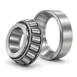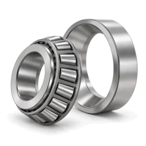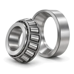

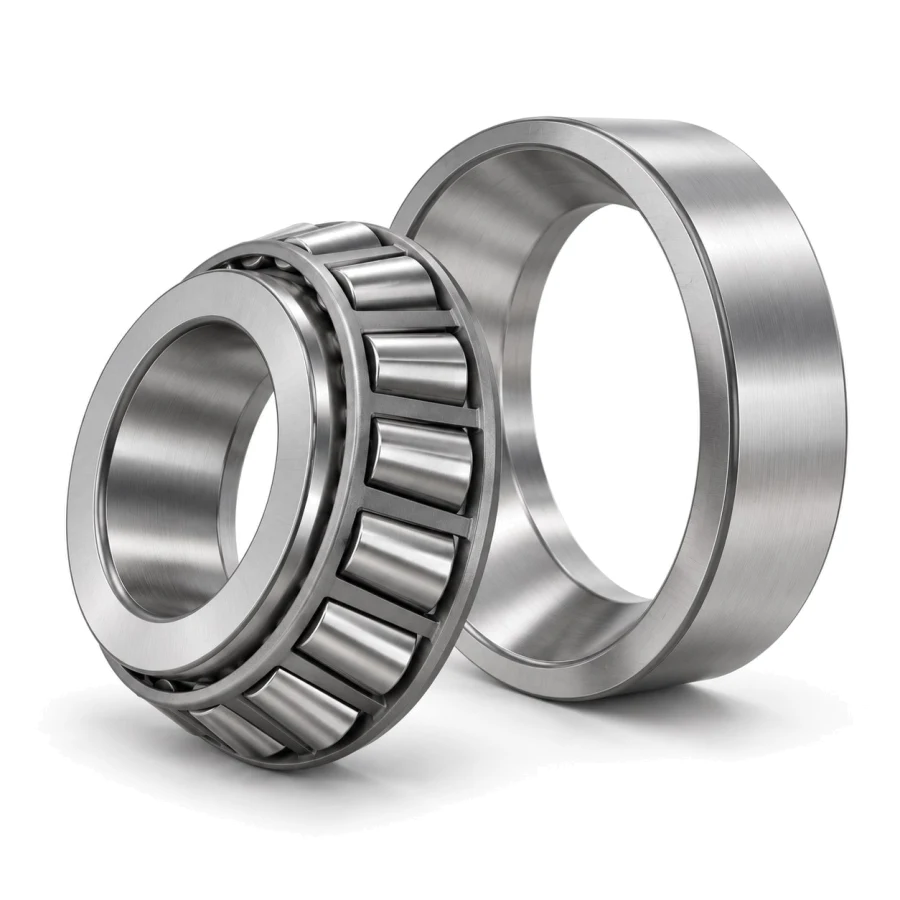
33120 Tapered Roller Bearing Overview
Built as a separable single-row tapered roller assembly on a 100 mm straight cylindrical bore, 33120 packs wider rollers into a compact 100 × 165 × 52 mm overall envelope (T = 52 mm, B = 52 mm, cup width C = 40 mm, 4.29 kg). Catalogue capacity reaches Cr = 325 kN and Cor = 523 kN with load center a = 40.1 mm; limiting speeds and db are confirmed per operating lubrication.
33120 Technical Specifications & Dimensions
| Parameter Category | Technical Parameter (Symbol) | Catalogue Reference Value |
|---|---|---|
| Boundary Dimensions & Weight | Bore diameter (d) | 100 mm |
| Boundary Dimensions & Weight | Outside diameter (D) | 165 mm |
| Boundary Dimensions & Weight | Inner-ring width (B) | 52 mm |
| Boundary Dimensions & Weight | Overall width (T) | 52 mm |
| Boundary Dimensions & Weight | Outer-ring width (C) | 40 mm |
| Boundary Dimensions & Weight | Reference mass (Weight) | 4.29 kg |
| Load Ratings & Limiting Speeds | Basic dynamic load rating (Cr) | 325 kN |
| Load Ratings & Limiting Speeds | Basic static load rating (Cor) | 523 kN |
| Abutment & Fillet Dimensions | Shaft abutment diameter (da) | 112 mm |
| Abutment & Fillet Dimensions | Housing abutment diameter (Da) | 142 mm |
| Abutment & Fillet Dimensions | Housing abutment reference diameter (Db) | 159 mm |
| Abutment & Fillet Dimensions | Minimum chamfer dimension (r12) | 2.5 mm |
| Abutment & Fillet Dimensions | Minimum flange chamfer (r34) | 2 mm |
| Abutment & Fillet Dimensions | Maximum fillet radius (ra) | 2 mm |
| Abutment & Fillet Dimensions | Maximum flange fillet radius (rb) | 2 mm |
| Abutment & Fillet Dimensions | Load center distance (a) | 40.1 mm |
| Calculation Factors | Calculation factor (e) | 0.41 |
| Calculation Factors | Axial load factor (static) (Y0) | 0.81 |
| Calculation Factors | Axial load factor (Y) | 1.48 |
Data source: ZQM Bearings online catalogue database (factory PDF catalogue v1). Load ratings, limiting speeds, and parameters without individual test records serve as catalogue reference values; verify shaft/housing shoulders (da, db, Da), tolerances, internal clearance, and drawings prior to ordering.
Designation Breakdown & 100 mm Bore Selection
Key execution codes for 33120 and engineering comparison across 100 mm bore catalogue alternatives:
| Attribute | Code / Option | Engineering Notes |
|---|---|---|
| Assembly Design | 33120 (Cone + Cup) |
Separable inner cone with rollers and outer cup; straight cylindrical bore; overall width T = 52 mm, cone B = 52 mm, cup C = 40 mm |
| Axial Pairing | Back-to-Back (DB) / Face-to-Face (DF) | Single-row tapered geometry carries axial thrust in one direction; pair opposed units and set axial preload/clearance |
| Load Center & Factors | a = 40.1 mm | Effective pressure cone center at 40.1 mm with e = 0.41, Y = 1.48, Y0 = 0.81 |
Across 100 mm metric tapered units, this model matches the heavy Cr = 325 kN capacity of 32220 (180 mm OD) inside a 15 mm smaller 165 mm outer diameter, saving housing space over 30220 (Cr 255 kN) and 32020X (Cr 176 kN).
| Catalogue Unit | Envelope & Mass | Ratings & Grease Limit |
|---|---|---|
| 33120 (Current) | 100 × 165 × 52 mm · 4.29 kg | Cr 325 kN · C0r 523 kN · Contact us for specifications |
| 30220 | 100 × 180 × 37 mm · 3.78 kg | Cr 255 kN · C0r 330 kN · Contact us for specifications |
| 32220 | 100 × 180 × 49 mm · 5.05 kg | Cr 325 kN · C0r 450 kN · Contact us for specifications |
| 32020X | 100 × 150 × 32 mm · 1.95 kg | Cr 176 kN · C0r 294 kN · Contact us for specifications |
Brand Cross-Reference & Interchangeability
Manufacturer designations sharing the 100 × 165 × 52 mm nominal ISO boundary envelope (full product catalog):
| Manufacturer | Reference Code | Verification Scope |
|---|---|---|
| ZQM Bearings | 33120 |
Single-row tapered cone and cup per ISO 15 / ISO 355 boundary envelope |
| SKF | 33120 | Standard metric tapered series reference; verify internal contact angle |
| FAG / Schaeffler | 33120-XL | X-life metric tapered series reference |
| NSK | HR33120J | High-capacity metric tapered reference |
| NTN / Timken | 4T-33120 / 33120M | Metric tapered series dimensional peer |
Engineering Interchange Disclaimer: Cross-reference for identification only. Verify interchangeability with engineering drawings. Listed references share nominal ISO boundary dimensions (100 × 165 × 52 mm) only; internal geometry, cage execution, and load ratings vary by manufacturer.
Industrial Applications & Mounting Guidance (100 mm Shaft Class)
Primary machinery roles and field mounting practices matched to this 100 × 165 × 52 mm assembly:
| Target Machinery | Operating Duty Profile | Mounting & Lubrication Practice |
|---|---|---|
| Heavy Truck Axles & Differential Pinions | Combined radial bevel-gear loads plus single-direction thrust | Mount opposed in back-to-back (DB) or face-to-face (DF) pairs and set end-play preload |
| Industrial Helical-Bevel Gearboxes | High axial gear thrust within constrained 165 mm housing bores | Verify axial factor Y = 1.48 and static factor Y0 = 0.81 against peak pinion torque |
| Machine Tool Spindles & Roll Neck Chocks | High axial rigidity requiring separable cone/cup installation | Seat housing cup firmly against Da max 142 mm / Db min 159 mm; verify mounted axial clearance or preload per equipment assembly drawings |
For reliable service life under ISO 281 fatigue calculations, maintain clean oil filtration, monitor housing temperature stabilization after initial run-in, and verify shaft journal roundness and shoulder squareness against the published abutment geometry before final press or sleeve installation. Mounted axial clearance or preload must be set and verified during assembly according to the equipment layout drawing (using shims or locknut adjustment), while export batches include protective rust-inhibitor coating, individual VCI wrapping, and heavy-duty plywood crating tailored to sea or air transit.
Pre-Order Engineering Checklist
Confirm these three verification checkpoints with our engineering desk prior to scheduling factory dispatch for this 100 × 165 × 52 mm model:
| Checkpoint | Parameters to Confirm | Engineering Purpose |
|---|---|---|
| 1. Code & Clearance | Specify 33120, C0/C3/C4 play, and straight bore |
Aligns mounted internal play with shaft interference and running ΔT |
| 2. Shoulder & Fit Limits | Verify da 112 mm, Da 142 mm, Db 159 mm, ra 2 mm; db: Contact us for specifications | Prevents chamfer interference and inner-ring creep |
| 3. Quantity & QC Scope | Unit mass 4.29 kg; state batch qty, EXW/FOB/CIF terms, and CMM/UT/hardness needs | Confirms pallet crating, MOQ lead time, and inspection records |
Frequently Asked Questions
What are the exact widths T, B, C and mass of this 100 mm tapered model?
ZQM catalogue records specify 100 mm straight bore, 165 mm OD, overall width T = 52 mm, cone width B = 52 mm, cup width C = 40 mm, and 4.29 kg unit mass.
What are the load center (a) and limiting speeds of this tapered unit?
The effective load center is a = 40.1 mm with calculation factor e = 0.41 and Y = 1.48. Limiting grease/oil speeds are unquoted in the database—Contact us for specifications.
Which shoulder dimensions govern cone and cup mounting?
Published limits list da reference = 112 mm (limit direction to be confirmed per assembly drawing), Da max = 142 mm, Db min = 159 mm, chamfers r1,2 = 2.5 mm / r3,4 = 2 mm, and fillets ra/rb = 2 mm; for db, Contact us for specifications.
How are paired preload, MOQ, and dimensional QC verified for 100 mm tapered orders?
Because single-row tapered units carry axial thrust in one direction only, buyers normally order matched DB/DF pairs or adjust shims during gearbox assembly. Contact ZQM for speed verification, export packaging, MOQ, and CMM/hardness QC reports.