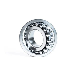

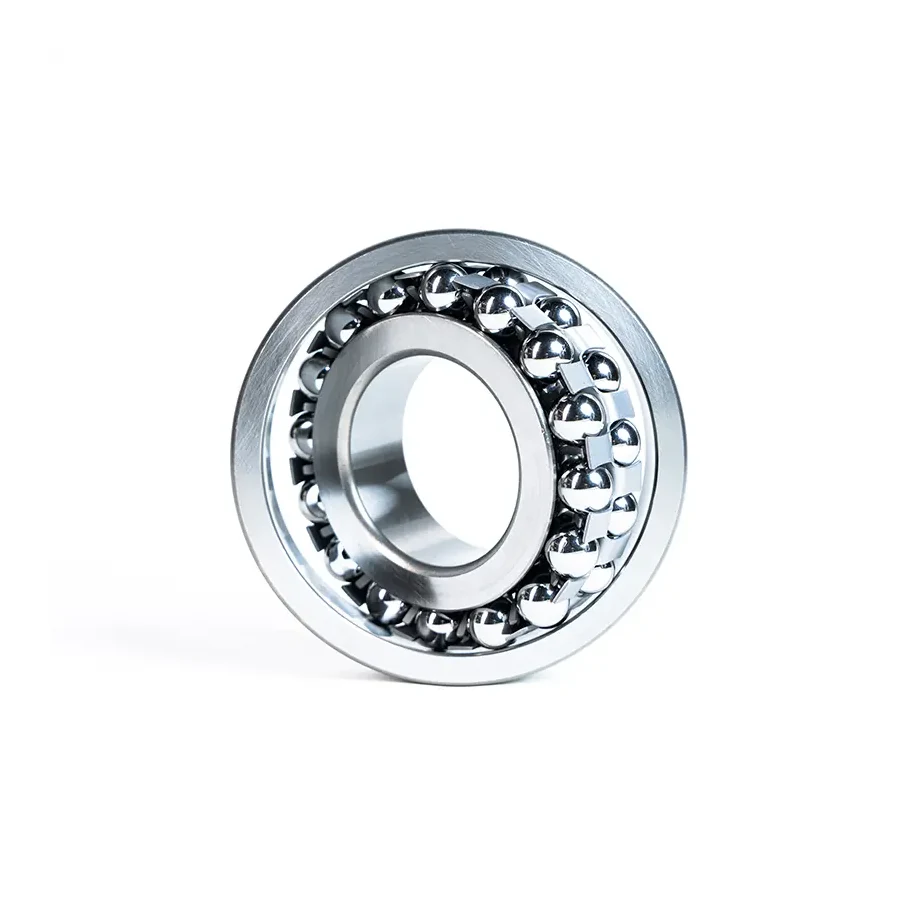
The 1310 self-aligning ball bearing (50 × 110 × 27 mm, ISO 15 Dimension Series 03) steps up radial section height and ball diameter substantially beyond the lighter 1210 (50 × 90 × 20 mm) on the same 50 mm shaft. Engineered for baghouse dust-collector exhausters and industrial boiler induced-draft (ID) blower impellers, it pairs 2.5°–3° misalignment resilience with sturdier rolling elements—available as straight-bore 1310 or 1310K (1:12 taper) with an H310 sleeve for 45 mm shafting.
| ISO 15 Dimension | Symbol | 1310 Nominal | Series 03 Remarks |
|---|---|---|---|
| Bore Diameter | d | 50 mm | Straight cylindrical fit |
| Outside Diameter | D | 110 mm | 20 mm larger OD than light 1210 |
| Width | B | 27 mm | Check ball side-protrusion past faces |
| Tapered Bore Option | 1310K | 1:12 Taper | Pairs with H310 sleeve (45 mm plain shaft) |
| Rolling Contact | Double-Row Ball | Sphered Outer Ring | Point contact (p = 3); lower friction than SRB |
| Load Ratings & Cage | Cr / C0r / Cage | Confirmed on Factory Print | High-temp steel or brass cage verified at quote |
1310 Series 03 Strength & Critical Ball Protrusion Check
Baghouse collectors and coal- or biomass-fired boiler ID fans move gritty flue gas that gradually cakes onto impeller blades. Even between scheduled washdowns, slight dust accretion creates rotating unbalance forces that overwhelm narrow 12-series bearings. Stepping up to the 50 × 110 × 27 mm Series 03 envelope equips the 1310 with noticeably beefier double-row balls and thicker ring walls while keeping ball-bearing friction low enough to run cleanly at blower speeds.
Crucial Installation Geometry Warning: On certain Series 13 self-aligning ball bearings, the large rolling balls project slightly beyond the nominal 27 mm inner and outer ring side faces. Before clamping adjacent locknuts, oil flingers, end covers, or spacer collars onto a 1310 assembly, verify the exact axial ball-protrusion dimension on our factory engineering drawing so stationary components never scrape rotating balls. Similarly, boiler ID drafts conduct heat along the shaft—avoid standard polyamide retainers (~120 °C limit) whenever pedestal temperatures rise; request stamped steel or machined brass cages instead.
1310 Cross-Reference for Exhaust Fan & Boiler OEMs
Plant reliability engineers replacing failed blower bearings in SNL 512/610-class pedestals frequently verify these ISO 15 Series 03 codes:
| Brand / Standard | Cylindrical Bore | 1:12 Tapered Bore | Engineering Comparison Notes |
|---|---|---|---|
| ZQM Bearings | 1310 | 1310K | Confirm steel/brass cage & ball protrusion on drawing |
| SKF | 1310 EKTN9 (taper) / 1310 ETN9 | 1310 EKTN9 | TN9 polyamide limit ~120 °C; check M/steel variants |
| FAG / Schaeffler | 1310-TVH / 1310-M | 1310-K-TVH / 1310-K-M | TVH = polyamide; M = machined brass cage |
| NSK / NTN | 1310 | 1310K | Confirm C3 thermal clearance & retainer alloy |
| Legacy GB Code | 1310 | 11310 | Former Chinese standard designation |
Dimensional Disclaimer: Listing these part numbers confirms shared ISO 15 envelope boundaries (50 × 110 × 27 mm) alone. Retainer heat tolerance, side-protrusion allowance, internal clearance, and dynamic load capacities differ by brand and require engineering sign-off prior to substitution.
Induced-Draft Blower Cooling, Thermal Growth & SRB Threshold
Overhung boiler exhaust impellers located inside heavy industrial thermal and cement plants rely on heat-slinger discs between the hot scroll and the inboard bearing pedestal. Even with a cooling disc, inner rings run hotter than air-cooled outer housings, shrinking radial clearance—hence C3 clearance is widely specified on 1310 ID fan journals once thermal fit calculations are checked.
Mount the locating bearing nearest the drive coupling away from the hot flue gas, leaving the fan-side 1310 free to slide inside its housing bore as the shaft lengthens. Where extreme fly-ash abrasion triggers violent impeller unbalance or shock loads exceed ball-bearing capability, inspect whether your pedestal warrants transitioning to a 22310 or 21310 spherical roller bearing.
Requesting a 1310 Boiler & Dust-Collector Specification Quote
Include five engineering facts with your inquiry: bore format (50 mm straight 1310 vs 1310K + H310 sleeve), expected bearing housing temperature, mandatory metal cage selection (steel or brass vs polymer), radial clearance grade (CN or C3), and required order volume. Our team sends back the confirmed factory drawing detailing axial ball protrusion and load ratings before manufacture.
Request 1310 Drawing & High-Temp Cage Quote
1310 Engineering FAQ for Industrial Exhaust Fans
Related Selection & Comparison: Need an extra-wide 40 mm footprint on a 50 mm shaft? Compare 2310, or step down to compact 90 mm OD via 1210; check heavy shock roller upgrades in Spherical Roller Bearings.
How does 1310 differ from 1210 on the same 50 mm fan shaft?
Both share a 50 mm bore, but 1310 belongs to ISO 15 Series 03 with a 110 mm OD and 27 mm width versus 1210’s 90 mm OD and 20 mm width. That larger cross-section gives 1310 substantially higher radial stamina under unbalanced blower impellers.
Why must I check ball side-protrusion when installing a 1310?
Because the large double-row balls in medium-heavy Series 13 designs can sit slightly proud of the 27 mm nominal ring width, unverified spacer sleeves, oil flingers, or seal rings could collide with the balls unless clearance is checked against the formal factory drawing.
Which adapter sleeve fits the 1310K 1:12 tapered bore?
The 1310K pairs with an H310 metric adapter sleeve to mount cleanly onto a 45 mm plain shaft—note that the narrower H210 sleeve used on 1210K is too short for the 27 mm wide 1310K.
Is a polyamide cage safe for boiler induced-draft fans?
Generally no if conducted flue heat pushes bearing temperature near or above 100–120 °C. Specify a stamped steel or machined brass cage on your 1310 order drawing for thermal safety margin.