

In crane hook swivels, heavy gate-valve stems, mechanical screw jacks, and slow-speed vertical turntables, axial thrust dominates the bearing budget while radial loads are handled elsewhere. ISO 104 single-direction thrust ball bearings—spanning the 511 Extra-Light, 512 Light, 513 Medium, and 514 Heavy series—deliver an economical, low-friction, separable solution engineered specifically for pure unidirectional axial force. Yet three recurring engineering mistakes cause avoidable field failures: applying radial or eccentric loads beyond the Fr = 0 limit, reversing the shaft washer (d) and housing washer (D1 > d) after cleaning, and overlooking minimum axial load (Fa_min) skidding limits at elevated RPM.
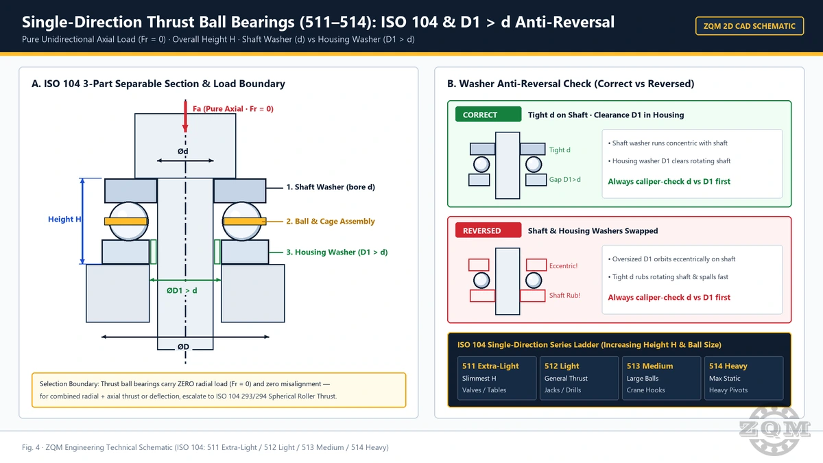
Decoding ISO 104 Series Scaling: 511 Extra-Light to 514 Heavy (Always Measured by Overall Height H)
Unlike radial ball and roller bearings specified by d × D × B, ISO 104 thrust bearings are dimensioned by bore d, outside diameter D, and overall height H. Across our thrust ball bearing range, the first three digits define the cross-section series for a given shaft diameter:
511Extra-Light Series: Smallest outside diameterDand slimmest overall heightH—chosen when axial stack space is tight and pure axial loads remain light to moderate.512Light Series: The everyday industrial baseline, offering larger balls and deeper raceways for valve actuators, screw jacks, and standard crane hook blocks.513Medium Series: Substantially heavier radial section and heightHengineered for high unidirectional thrust on heavy industrial gates, hoists, and presses.514Heavy Series: Maximum ISO 104 ball thrust cross-section for extreme pure axial static and low-speed shock loads where radial space allows a larger outside diameterD.
To appreciate how dramatically section strength scales on an identical 60 mm shaft, compare all four verified ISO 104 series side by side: 51112 Extra-Light (60 × 85 × 17 mm H), 51212 Light (60 × 95 × 26 mm H), 51312 Medium (60 × 110 × 35 mm H), and 51412 Heavy (60 × 130 × 51 mm H). Moving from 51112 to 51412 triples the overall height H from 17 mm to 51 mm on the exact same 60 mm shaft bore.
Verified ISO 104 Dimension Table: 511 / 512 / 513 / 514 Core Models
Every dimension below follows ISO 104 boundary standards (d × D × H in millimeters). Select any model designation to inspect product specifications and request engineering support:
| ISO 104 Model | Series Classification | d × D × H (mm) | Application and Sizing Note |
|---|---|---|---|
| 51110 | 511 Extra-Light | 50 × 70 × 14 | Compact axial envelope; light pure thrust |
| 51112 | 511 Extra-Light | 60 × 85 × 17 | Compact 60 mm bore baseline (compare 51212–51412) |
| 51116 | 511 Extra-Light | 80 × 105 × 19 | Low height H for valve stems and rotary tables |
| 51120 | 511 Extra-Light | 100 × 135 × 25 | Slim radial section for 100 mm vertical shafts |
| 51124 | 511 Extra-Light | 120 × 155 × 25 | Large-bore compact height H = 25 mm |
| 51210 | 512 Light | 50 × 78 × 22 | Larger balls and deeper raceway than 51110 |
| 51212 | 512 Light | 60 × 95 × 26 | Workhorse 60 mm bore for jacks and crane hooks |
| 51216 | 512 Light | 80 × 115 × 28 | Balanced OD and height H for industrial valves |
| 51220 | 512 Light | 100 × 150 × 38 | Substantial pure axial thrust on 100 mm shafts |
| 51312 | 513 Medium | 60 × 110 × 35 | High-thrust 60 mm section for heavy hook blocks |
| 51316 | 513 Medium | 80 × 140 × 44 | Heavy-duty gate valves and vertical screw jacks |
| 51412 | 514 Heavy | 60 × 130 × 51 | Maximum ISO 104 ball thrust section on 60 mm shaft |
The Non-Negotiable Boundary: Pure Unidirectional Axial Load (Fr = 0) and When to Escalate
Because the flat-backed shaft and housing washers hold the balls in opposing axial grooves at a 90° contact angle, a single-direction thrust ball bearing carries pure unidirectional axial load only (Fr = 0). It offers zero radial stiffness, cannot sustain reversing axial thrust on its own, and tolerates virtually no shaft-to-housing angular misalignment (any shoulder out-of-squareness concentrates thrust onto a narrow arc of balls and accelerates spalling).
- Ideal when a separate radial bearing guides the shaft and axial thrust acts cleanly in one direction.
- Requires square, rigid shaft shoulders and housing seats; excelling in crane hooks, screw jacks, gate valves, and turntables.
- Heavy combined thrust + shaft deflection: Upgrade to ISO 104 293/294 Spherical Roller Thrust Bearings (self-aligning, carries simultaneous radial load alongside massive axial thrust).
- Higher RPM + bidirectional axial + radial rigidity: Upgrade to back-to-back (
DB) or face-to-face (DF) paired72/73 BMangular contact ball bearings.
Separable Washer Anti-Reversal Rule (D1 > d): Preventing a Classic Field Error
One practical convenience of ISO 104 single-direction thrust ball bearings is their separable three-piece construction: shaft washer, ball-and-cage thrust assembly, and housing washer can be mounted independently. Unfortunately, that same separability invites one of the most common overhaul errors in maintenance shops—washing the two rings in the same solvent tray and putting them back upside down.
Although both washers look nearly identical at a glance, their bores are intentionally different:
- Shaft Washer (Tight Bore
d): Ground to a tight nominal boredso it centers accurately on the rotating shaft and seats flush against the rotating shaft shoulder. - Housing Washer (Clearance Bore
D1 > d): Manufactured with a slightly larger boreD1(typically0.2–2.0 mmlarger thanddepending on size) so it seats concentrically in the stationary housing bore without contacting the rotating shaft.
What happens if you reverse them? Placing the clearance-bore housing washer (D1 > d) onto the rotating shaft leaves it radially loose and eccentric, while seating the tight-bore shaft washer (d) in the stationary housing risks direct metallic rubbing between the stationary ring bore and the rotating shaft. Under load, the balls orbit off-center across the raceway groove shoulders—triggering rapid heat rise, shaft scoring, cage fracture, and spalling within hours.
10-Second Shop Verification Rule: Always caliper-check both washer inside diameters immediately prior to assembly. The smaller bore (d) goes onto the rotating shaft every single time; the larger clearance bore (D1 > d) seats in the stationary housing every single time. Check that both backing shoulders are flat, clean, and perpendicular to the shaft axis before closing the housing.
Minimum Axial Load (Fa_min) and Centrifugal Ball-Skidding Limits
Unlike radial bearings where gravity and fit keep rolling elements tracking smoothly, balls in a 90° thrust ball bearing experience direct outward centrifugal force as rotational speed rises. If the applied axial thrust drops below the bearing’s minimum axial load (Fa_min) while spinning, centrifugal force and gyroscopic moments cause the balls to slide across the raceways instead of rolling cleanly—producing smeared raceway bands, micro-welding, and accelerated cage wear.
In practical machine design, that kinematic limit explains two rules of thumb:
- Ideal Applications: Slow-to-moderate-speed equipment carrying steady unidirectional thrust—such as crane hook blocks under suspended load, vertical screw jacks, industrial gate and globe valves, and slow indexing turntables—stays comfortably above
Fa_minand below centrifugal skidding speeds. - Horizontal Shafts or Lightly Loaded High-Speed Equipment: If a thrust ball bearing is mounted on a horizontal shaft (where gravity provides zero axial preload) or runs unloaded at elevated RPM, engineers must apply constant spring preloading to maintain
Fa_min—or transition to paired angular contact ball bearings better suited for high-speed rotation.
Need to decode cage, tolerance, or washer-execution suffixes on an existing OEM thrust bearing print? Use our Bearing Suffix Decoder before preparing your replacement inquiry.
Pre-Order Engineering Checklist for 511 / 512 / 513 / 514 Procurement
Before placing an order or substituting a legacy thrust bearing, verify these six engineering points with ZQM Bearings (all shipments follow our documented inspection standards detailed on Quality and Inspection):
- Exact ISO 104 Model and Overall Height
H: Confirm full designation (511/512/513/514) and verifyd × D × Hagainst the housing stack. - Load Direction and Radial Support Check: Confirm pure unidirectional axial thrust (
Fr = 0) with independent radial shaft guidance; if reversing thrust or radial load exists, ask our engineers about double-direction thrust units,293/294roller thrust bearings, or paired angular contact bearings. - Washer Seating Geometry: State whether the stationary housing seat requires a standard flat housing washer or a sphered housing washer with seating ring (
532/533/534+Useries) to compensate for static seat misalignment. - Operating Speed and Minimum Axial Load: Share rotational RPM and minimum continuous axial force so
Fa_minand lubrication suitability can be checked. - Cage Execution Preference: Confirm pressed steel versus machined brass cage per application temperature, vibration, and drawing specification rather than assuming material from base digits alone.
- Lubrication and Contamination Sealing: Specify grease relubrication intervals or oil-bath supply, especially on outdoor crane hooks and vertical valve actuators exposed to moisture or grit.
Frequently Asked Questions
Can a 511, 512, 513, or 514 single-direction thrust ball bearing carry any radial load?
No. ISO 104 single-direction thrust ball bearings are strictly designed for pure unidirectional axial load (Fr = 0). They provide zero radial shaft support and cannot tolerate angular misalignment—radial forces must always be carried by a separate radial bearing, or you should escalate to 293/294 spherical roller thrust bearings or paired 72/73 BM angular contact ball bearings.
How do I tell the shaft washer and housing washer apart to avoid reverse installation?
Measure both washer bores with a caliper before mounting. The shaft washer has the exact tight nominal bore d to seat cleanly on the rotating shaft shoulder, while the housing washer has a slightly larger clearance bore D1 (D1 > d) so it sits inside the stationary housing without rubbing against the rotating shaft.
What happens if the shaft washer and housing washer are accidentally swapped during reassembly?
Installing the clearance-bore housing washer (D1 > d) on the rotating shaft lets it run off-center, while mounting the tight-bore shaft washer (d) in the stationary housing can cause bore rubbing against the rotating shaft. The result is eccentric ball orbiting, asymmetric raceway loading, rapid overheating, and early spalling.
How do the 511 Extra-Light, 512 Light, 513 Medium, and 514 Heavy series differ on the same shaft size?
For the exact same 60 mm bore, ISO 104 scales both outside diameter D and overall height H upward across the four series: 51112 Extra-Light measures 60 × 85 × 17 mm H, 51212 Light measures 60 × 95 × 26 mm H, 51312 Medium measures 60 × 110 × 35 mm H, and 51412 Heavy reaches 60 × 130 × 51 mm H—accommodating progressively larger balls and heavier pure axial loads.
Why do thrust ball bearings require a minimum axial load (Fa_min) when running at higher RPM?
Because the balls orbit perpendicular to the shaft axis, centrifugal force drives them radially outward as speed climbs. Without sufficient continuous axial load (Fa_min) keeping balls seated firmly in the raceway grooves, sliding and gyroscopic skidding occur—causing raceway smearing and cage distress. That is why thrust ball bearings excel in slow-to-moderate-speed crane hooks, screw jacks, gate valves, and turntables.
Selecting ISO 104 Thrust Ball Bearings (511–514) or Escalating to 293/294 Roller Thrust?
Send your shaft diameter d, outside diameter D, overall height H, operating RPM, and axial load direction. ZQM engineers confirm washer geometry, cage execution, and order-matched inspection scope before quoting.