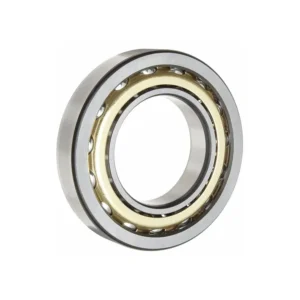

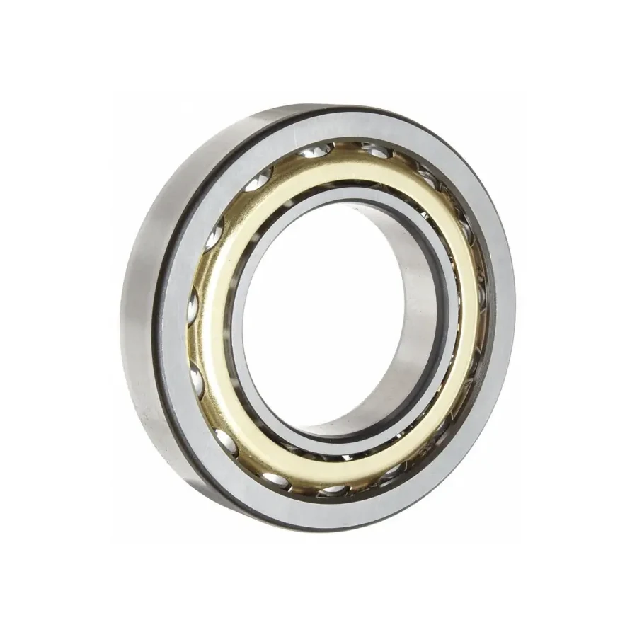
Engineered to the identical 100 × 180 × 34 mm ISO 02 envelope as 40° series bearings but tuned for cooler high-speed transmission, the 7220ACM (7220 ACM) single-row angular contact ball bearing weighs 3.74 kg and carries catalog ratings of Cr = 114 kN and C0r = 130 kN. Its shallower 25° contact angle (AC) paired with a solid machined brass cage (M) lowers spin-to-roll friction on CNC horizontal boring and milling gearbox intermediate and main drive shafts while preserving strong combined radial-axial rigidity.
7220ACM Technical Specifications & Dimensions
| Parameter Category | Technical Parameter (Symbol) | Catalogue Reference Value |
|---|---|---|
| Boundary Dimensions & Weight | Bore diameter (d) | 100 mm |
| Boundary Dimensions & Weight | Outside diameter (D) | 180 mm |
| Boundary Dimensions & Weight | Width (B) | 34 mm |
| Boundary Dimensions & Weight | Reference mass (Weight) | 3.74 kg |
| Load Ratings & Limiting Speeds | Basic dynamic load rating (Cr) | 114 kN |
| Load Ratings & Limiting Speeds | Basic static load rating (Cor) | 130 kN |
| Load Ratings & Limiting Speeds | Limiting speed (grease) | 3000 rpm |
| Load Ratings & Limiting Speeds | Limiting speed (oil) | 4000 rpm |
| Abutment & Fillet Dimensions | Shaft abutment diameter (da) | 112 mm |
| Abutment & Fillet Dimensions | Housing abutment diameter (Da) | 168 mm |
| Abutment & Fillet Dimensions | Minimum chamfer dimension (r12) | 2.1 mm |
| Abutment & Fillet Dimensions | Minimum flange chamfer (r34) | 1.1 mm |
| Abutment & Fillet Dimensions | Maximum fillet radius (ra) | 2 mm |
| Abutment & Fillet Dimensions | Load center distance (a) | 49.6 mm |
| Calculation Factors | Calculation factor (e) | 0.68 |
| Calculation Factors | Axial load factor (static) (Y0) | 0.38 |
| Calculation Factors | Axial load factor (Y) | 0.87 |
| Calculation Factors | Radial load factor (X) | 0.42 |
Data source: ZQM Bearings online catalogue database (factory PDF catalogue v1). Load ratings, limiting speeds, and parameters without individual test records serve as catalogue reference values; verify shaft/housing shoulders (da, db, Da), tolerances, internal clearance, and drawings prior to ordering.
Inside 7220ACM: 25° Contact Angle Dynamics vs. 40° Counterparts
While both 7220ACM and 7220BM fit a 100 mm shaft and 180 mm housing bore, the AC (25°) internal raceway geometry shifts the load behavior dramatically. Lowering the contact angle from 40° to 25° pulls the load center inward to a = 49.6 mm and decreases gyroscopic ball spin at elevated shaft speeds, reducing thermal growth inside closed machine-tool gearboxes.
- Higher Catalog Load Capacity in the Same Envelope: The 25° ball-to-raceway geometry achieves 114 kN dynamic and 130 kN static catalog ratings (compared with 100 kN / 114 kN for the 40° 7220BM), making it well suited when radial gear-mesh forces rival axial helical thrust.
- Calculation Constants: Catalog ISO 281 / ISO 76 factors are e = 0.68, X = 0.42, Y = 0.87, and Y0 = 0.38, reflecting greater sensitivity to radial components alongside dependable unidirectional thrust support.
- Machined Brass Cage & Speed Ceiling: Rated to 3,000 r/min with grease and 4,000 r/min with oil, the solid M brass cage runs quietly under rapid spindle acceleration and braking cycles without pocket chatter.
CNC Horizontal Boring & Milling Gearbox Shaft Integration
Horizontal machining centers and floor-type boring mills rely on two-speed or multi-step headstock gearboxes to deliver full torque in heavy roughing cuts while spinning rapidly during finishing passes. Placing paired 7220ACM bearings on the primary input or intermediate helical gear shaft balances radial tooth separation forces against moderate bidirectional axial thrust when arranged back-to-back (DB) or face-to-face (DF).
To prevent thermal preload escalation across long continuous cutting shifts, machinists must hold housing shoulder Da ≤ 168 mm, shaft abutment da ≥ 112 mm, and shoulder fillet radius ra ≤ 2 mm against the bearing’s r1,2 min = 2.1 mm and r3,4 min = 1.1 mm chamfers. Because a single 7220ACM carries axial thrust in one direction only, every locating gearbox shaft requires an opposed paired arrangement—or tandem DT paired against an opposing third unit—adjusted to the builder’s thermal axial clearance target. See how we support industrial machinery makers on our equipment applications hub.
Equivalent Designations & 7220ACM Contact-Angle Check
| Brand / Standard | Nominal Envelope Code | Contact Angle & Cage Comparison (100 × 180 × 34 mm) |
|---|---|---|
| ZQM / GB/T 292 | 7220ACM | 25° contact angle (AC), solid machined brass cage (M) |
| SKF | 7220 ACD (precision) / 7220 BECBM (40°) | Verify angle! Standard industrial SKF 7220 is 40° (B); 25° (ACD) is typically precision class |
| NSK | 7220AM (30°) / 7220A5 (25°) | Standard NSK A = 30° with M brass cage; A5 denotes 25° contact angle |
| FAG / Schaeffler | 7220-B-MP (40°) / B7220-E (25°) | Standard industrial FAG uses 40° (B); 25° (E) appears in spindle-class series |
| NTN | 7220L1 (30°) | 30° standard angle with machined brass cage (L1); check axial load ratio |
Engineering Caution: Only the ISO 15 boundary dimensions (100 × 180 × 34 mm) align across the table above. Switching between 25° (AC), 30° (A), and 40° (B) alters the axial-to-radial stiffness ratio and load-center distance a; always validate precision grade (P0/P6/P5) and contact angle against the headstock assembly print before substituting.
Procurement Checklist for Machine-Tool Builders & Rebuilders
When requesting a quotation for 7220ACM gearbox bearings, specify your target running tolerance grade (standard P0, P6, or P5), matched-set configuration (DB, DF, or DT with defined preload/clearance), and whether recirculating gear oil or synthetic grease lubricates the shaft. ZQM supplies machine-tool OEM production lots as well as small-batch rebuild kits for CNC service shops. Share your drawing or bill of materials through our direct inquiry portal.
7220ACM Engineering Questions
Related Selection & Comparison: For higher unidirectional axial thrust in the identical 100 × 180 × 34 mm housing, compare the 40° 7220BM, explore precision spindle architectures in Precision Machine Tools, or check all Angular Contact Ball Bearings.
How does 7220ACM differ mechanically from 7220BM of the exact same size?
Both measure 100 × 180 × 34 mm with machined brass cages, but 7220ACM uses a 25° contact angle (a = 49.6 mm, e = 0.68, Cr = 114 kN, 3.74 kg) whereas 7220BM uses a 40° angle (a = 75.7 mm, e = 1.14, Cr = 100 kN, 4.00 kg). Choose 7220ACM when radial gear loads and cooler high-RPM running take precedence over extreme pure axial thrust.
Can a single 7220ACM be mounted alone on a boring-mill gearbox shaft?
No. Single-row angular contact bearings only resist axial force in one direction. Machine-tool drive shafts must mount 7220ACM in opposed pairs (back-to-back DB for higher moment stiffness or face-to-face DF when minor housing misalignment exists) to locate helical gears in both directions.
Is 7220ACM suitable for oil-jet or circulating gearbox lubrication up to 4,000 r/min?
Yes—the catalog oil-lubrication limiting speed is 4,000 r/min (3,000 r/min for grease). Actual safe speed inside a CNC headstock also depends on preload tightness, oil-flow evacuation to prevent churning, and shaft/housing geometric runout.
What tolerance class and documentation can ZQM provide for 7220ACM orders?
Standard industrial stock is supplied with factory dimensional, radial runout, and hardness inspection records. If your boring-mill gearbox requires P6 or P5 accuracy grades or matched-pair serialization, note those requirements at RFQ stage so production lead time and inspection scope are confirmed upfront.