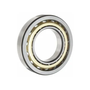

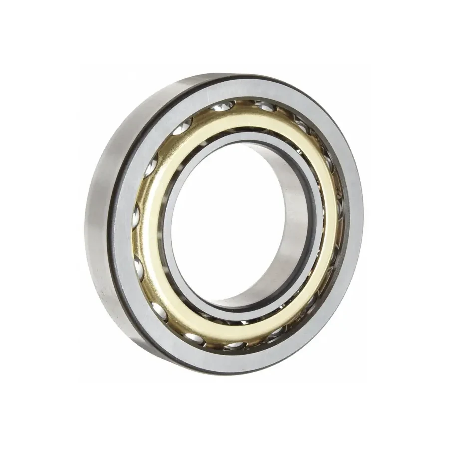
Built on the heavy ISO 03 cross-section for demanding mechanical power transmission, the 7320BM (7320 BM) single-row angular contact ball bearing spans 100 × 215 × 47 mm and weighs 8.41 kg per ring assembly. Delivering a 146 kN dynamic rating and substantial 178 kN static capacity across a 40° contact angle (B) with a solid machined brass cage (M), it serves as the primary bidirectional locating pair on heavy helical industrial gearbox input pinions where frequent torque reversals and shock loads exceed medium-series limits.
7320BM Technical Specifications & Dimensions
| Parameter Category | Technical Parameter (Symbol) | Catalogue Reference Value |
|---|---|---|
| Boundary Dimensions & Weight | Bore diameter (d) | 100 mm |
| Boundary Dimensions & Weight | Outside diameter (D) | 215 mm |
| Boundary Dimensions & Weight | Width (B) | 47 mm |
| Boundary Dimensions & Weight | Reference mass (Weight) | 8.41 kg |
| Load Ratings & Limiting Speeds | Basic dynamic load rating (Cr) | 146 kN |
| Load Ratings & Limiting Speeds | Basic static load rating (Cor) | 178 kN |
| Load Ratings & Limiting Speeds | Limiting speed (grease) | 2600 rpm |
| Load Ratings & Limiting Speeds | Limiting speed (oil) | 3600 rpm |
| Abutment & Fillet Dimensions | Shaft abutment diameter (da) | 114 mm |
| Abutment & Fillet Dimensions | Housing abutment diameter (Da) | 201 mm |
| Abutment & Fillet Dimensions | Minimum chamfer dimension (r12) | 3 mm |
| Abutment & Fillet Dimensions | Minimum flange chamfer (r34) | 1.1 mm |
| Abutment & Fillet Dimensions | Maximum fillet radius (ra) | 2.5 mm |
| Abutment & Fillet Dimensions | Load center distance (a) | 89.6 mm |
| Calculation Factors | Calculation factor (e) | 1.14 |
| Calculation Factors | Axial load factor (static) (Y0) | 0.26 |
| Calculation Factors | Axial load factor (Y) | 0.57 |
| Calculation Factors | Radial load factor (X) | 0.35 |
Data source: ZQM Bearings online catalogue database (factory PDF catalogue v1). Load ratings, limiting speeds, and parameters without individual test records serve as catalogue reference values; verify shaft/housing shoulders (da, db, Da), tolerances, internal clearance, and drawings prior to ordering.
7320BM Heavy 73-Series Capacity & Load-Center Span
Stepping up from the 7220BM (180 × 34 mm) to the 7320BM (215 × 47 mm) on the same 100 mm shaft journal increases ball complement size and ring wall thickness, boosting static load capacity by over 56% to 178 kN. That extra static reserve protects raceway shoulders from brinelling during jammed-conveyor emergency stops or direct-on-line motor starts.
- Wide Overturning Moment Base: At a 40° contact angle, the effective load center projects to a = 89.6 mm. Mounted back-to-back (DB) at the locating end of a high-speed helical pinion shaft, two 7320BM rings form a rigid axial-and-moment anchor while a floating cylindrical roller bearing carries radial mesh load at the opposite end.
- Shock-Tolerant Brass Retainer (M): Solid machined brass retains pocket integrity in splash-lubricated ISO VG 220–320 EP gear oils where metallic wear debris and torque spikes rapidly fatigue stamped sheet-metal cages.
- Speed & Rating Constants: Catalog limiting speeds stand at 2,600 r/min (grease) and 3,600 r/min (oil), paired with calculation factors e = 1.14, X = 0.35, Y = 0.57, and Y0 = 0.26.
Helical Speed-Reducer Input Pinion Locating Architecture
In heavy-duty parallel-shaft and bevel-helical reducers driving belt conveyors, rubber mixers, bucket elevators, and rolling-mill auxiliaries, the input pinion turns at motor speed (typically 1,000–1,800 r/min) while generating continuous axial tooth thrust that flips direction whenever braking or reversing occurs. Because an individual 7320BM supports axial force in one direction only, gearbox designers pair two matched 7320BM bearings—most commonly DB for rigid shaft positioning or DF where cast-iron housing bore distortion is anticipated.
When designing or re-machining the reducer end-cap and shaft step, observe catalog mounting boundaries: shaft abutment da ≥ 114 mm, housing shoulder Da ≤ 201 mm, and fillet radius ra ≤ 2.5 mm to clear the heavy r1,2 min = 3 mm and r3,4 min = 1.1 mm ring chamfers. A controlled radial clearance between the outer ring OD and housing bore is often employed when the 7320BM pair serves strictly as an axial locator alongside a dedicated radial roller bearing, ensuring the thrust pair is not overloaded by radial gear forces. Review heavy transmission applications on our power transmission & heavy industry overview.
7320BM International Cross-Reference Table
| Manufacturer | Cross-Reference Code | Envelope & Design Alignment (100 × 215 × 47 mm) |
|---|---|---|
| ZQM | 7320BM | 40° contact angle (B), solid machined brass cage (M) |
| SKF | 7320 BECBM / 7320 BM | 40° contact angle; BECBM = Explorer geometry, universally matchable, brass cage |
| FAG / Schaeffler | 7320-B-XL-MP / 7320-B-MP | 40° contact angle (B), X-life / solid machined brass cage (MP) |
| NSK | 7320BM / 7320BMG | 40° contact angle (B), machined brass cage (M); G = universal flush-ground |
| NTN | 7320BL1 / 7320BL1G | 40° contact angle (B), machined brass cage (L1) |
Technical Verification Note: Cross-listed designations share nominal ISO 15 boundary geometry (100 × 215 × 47 mm) only. Because reducer pinion pairs depend on exact end-face stickout to control paired axial clearance (CA/CB/CC) or light preload, always confirm matched-set coding and lubrication oil viscosity before mixing brands inside a gearbox rebuild.
Ordering 7320BM Locating Pairs from ZQM Bearings
To prevent gearbox reassembly delays, include four details with your 7320BM inquiry: paired arrangement (DB, DF, or DT), required paired axial clearance group (critical for warm gear-oil splash sumps), whether the outer ring operates as a pure axial locator or combined radial-axial bearing, and delivery schedule. ZQM stocks and manufactures 73-series heavy brass-cage bearings for gearbox service centers and industrial reducer OEMs with responsive batch traceability. Reach our engineering team via the ZQM quote contact form.
7320BM Frequently Asked Questions
Related Selection & Comparison: Compare medium 72-series 100 mm options via 7220BM or heavier 110 mm gear shafts via 7322BM, and review helical pinion layouts in our Industrial Gearboxes Hub.
When should a gearbox designer upgrade from 7220BM to 7320BM on a 100 mm pinion shaft?
Upgrade to 7320BM (215 × 47 mm, 8.41 kg) whenever high helix-angle gear thrust, frequent motor reversals, or start-up torque surges push static safety margins beyond the 7220BM’s 114 kN static rating. The 7320BM lifts static capacity to 178 kN and dynamic capacity to 146 kN on the same 100 mm bore.
Should a 7320BM locating pair in a helical reducer use DB or DF mounting?
Back-to-back (DB) is preferred on overhung input pinions because its 89.6 mm load-center projection maximizes resistance to shaft bending moments. Face-to-face (DF) is selected when housing bores may deflect slightly under load or when the pair sits strictly as a decoupled axial thrust cartridge.
Why does 7320BM require a larger shaft shoulder fillet check than 7220BM?
Because the 7320BM carries a heavier 03-series ring section, its minimum ring chamfer rises to r1,2 min = 3 mm (versus 2.1 mm on 7220BM), permitting a shaft/housing fillet radius up to ra max = 2.5 mm with da ≥ 114 mm and Da ≤ 201 mm.
Can ZQM supply 7320BM as factory-matched pairs with specified axial clearance for gearbox MRO?
Yes. Inform our sales engineers of your DB/DF pairing layout and desired axial clearance group (standard normal or enlarged clearance for hot EP gear-oil sumps) plus quantity—we fulfill single-reducer repair pairs as well as recurring OEM production releases.