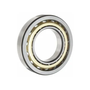

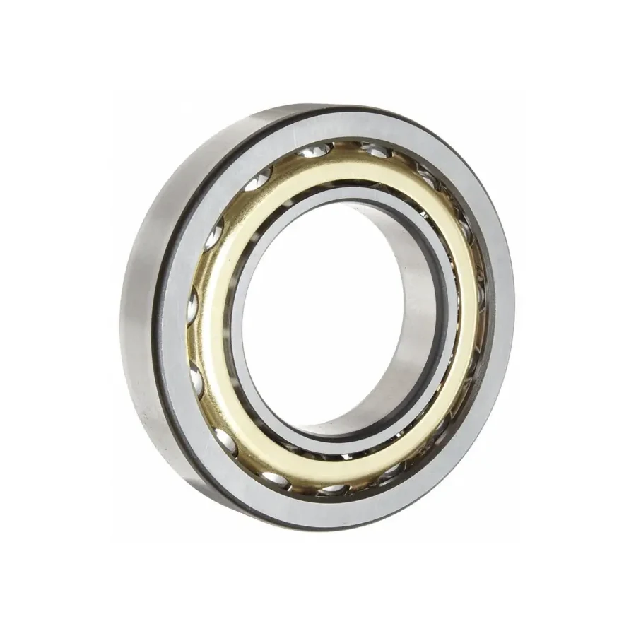
Combining a large 120 mm bore with an ultra-compact 180 mm outer diameter and 28 mm slim width, the 7024ACM (7024 ACM) single-row angular contact ball bearing weighs only 2.62 kg yet provides 77 kN dynamic capacity and 107 kN static rating. Configured with a low-drag 25° contact angle (AC) and balanced solid machined brass cage (M), it answers the demanding dynamics of centrifugal turbo-blowers, aeration compressors, and high-RPM industrial process fan impeller shafts where high first critical shaft speed requires a stiff 120 mm journal without massive outer-ring inertia.
7024ACM Technical Specifications & Dimensions
| Parameter Category | Technical Parameter (Symbol) | Catalogue Reference Value |
|---|---|---|
| Boundary Dimensions & Weight | Bore diameter (d) | 120 mm |
| Boundary Dimensions & Weight | Outside diameter (D) | 180 mm |
| Boundary Dimensions & Weight | Width (B) | 28 mm |
| Boundary Dimensions & Weight | Reference mass (Weight) | 2.62 kg |
| Load Ratings & Limiting Speeds | Basic dynamic load rating (Cr) | 77 kN |
| Load Ratings & Limiting Speeds | Basic static load rating (Cor) | 107 kN |
| Load Ratings & Limiting Speeds | Limiting speed (grease) | 2600 rpm |
| Load Ratings & Limiting Speeds | Limiting speed (oil) | 3600 rpm |
| Abutment & Fillet Dimensions | Shaft abutment diameter (da) | 130 mm |
| Abutment & Fillet Dimensions | Housing abutment diameter (Da) | 170 mm |
| Abutment & Fillet Dimensions | Minimum chamfer dimension (r12) | 2 mm |
| Abutment & Fillet Dimensions | Minimum flange chamfer (r34) | 1 mm |
| Abutment & Fillet Dimensions | Maximum fillet radius (ra) | 2 mm |
| Abutment & Fillet Dimensions | Load center distance (a) | 49.0 mm |
| Calculation Factors | Calculation factor (e) | 0.68 |
| Calculation Factors | Axial load factor (static) (Y0) | 0.38 |
| Calculation Factors | Axial load factor (Y) | 0.87 |
| Calculation Factors | Radial load factor (X) | 0.42 |
Data source: ZQM Bearings online catalogue database (factory PDF catalogue v1). Load ratings, limiting speeds, and parameters without individual test records serve as catalogue reference values; verify shaft/housing shoulders (da, db, Da), tolerances, internal clearance, and drawings prior to ordering.
Low-Inertia 7024ACM Geometry for High-RPM Impeller Shafts
Rotating fan and blower shafts face a classic rotordynamic trade-off: enlarging the shaft to 120 mm pushes bending critical speed safely above operating RPM, yet fitting a heavy 73-series bearing on that shaft skyrockets pitch-circle velocity (dm·n) and friction heat. With a radial cross-section of just 30 mm (180 mm OD vs. 260 mm on 7324BM) and a 2.62 kg mass, the 7024ACM keeps ball centrifugal force and oil churning remarkably low.
- 25° Contact Angle Speed Advantage (AC): Compared with 40° bearings, the 25° raceway contact geometry (load center a = 49.0 mm) reduces sliding spin friction across the ball-raceway ellipse during continuous high-speed blower operation up to 3,600 r/min (oil) or 2,600 r/min (grease).
- Precision Machined Brass Cage (M): Concentric turning produces clean mass balance across the retainer ring, curbing cage whirl and vibration amplitude on direct-drive and belt-driven blower rotors.
- Catalog Calculation Constants: ISO load factors are e = 0.68, X = 0.42, Y = 0.87, and Y0 = 0.38—tailored to aerodynamic rotors where radial impeller balance forces pair with continuous suction-side axial airflow thrust.
Blower Bearing Pedestal Assembly & Axial Preload Discipline
Multi-stage centrifugal blowers and wastewater aeration turbo-fans generate steady axial air thrust toward the inlet eye, occasionally reversing during surge-valve opening or rapid VFD coast-down. Because a single 7024ACM carries axial thrust in one direction only, blower pedestals install two matched 7024ACM bearings in a back-to-back (DB) locating cartridge (or DF where thermal housing tilt must be tolerated), paired with a floating bearing at the opposite pedestal end to allow unobstructed shaft thermal growth.
Observe exact mounting shoulder rules during pedestal boring and shaft grinding: shaft abutment da ≥ 130 mm, housing shoulder Da ≤ 170 mm, and fillet radius ra ≤ 2 mm to clear the r1,2 min = 2 mm and r3,4 min = 1 mm chamfers. On high-RPM air blowers, over-tightening axial preload or over-packing grease cavities causes rapid thermal runaway—maintain disciplined grease metering or circulating-oil cooling and verify residual paired clearance after bearing mounting. See related air-handling & rotating machinery applications on our industrial equipment overview.
7024ACM Brand Cross-Reference & Contact-Angle Check
| Manufacturer / Standard | Nominal Envelope Reference | Angle & Design Notes (120 × 180 × 28 mm) |
|---|---|---|
| ZQM / GB/T 292 | 7024ACM | 25° contact angle (AC), solid machined brass cage (M) |
| SKF | 7024 ACD (precision) / 7024 CD (15°) | Check precision class & angle: ACD = 25°, CD = 15°; verify cage material |
| FAG / Schaeffler | B7024-E (25°) / 7024-B-MP (40°) | E = 25° precision spindle series; B = 40° industrial with brass MP cage |
| NSK | 7024A5 (25°) / 7024AM (30°) | A5 = 25° contact angle; standard AM = 30° with machined brass cage |
| NTN | 7024L1 (30°) / 7024BL1 (40°) | Machined brass cage (L1); check contact angle difference vs. 25° AC |
Interchange Verification Disclaimer: Cross-listed part numbers align on ISO 15 nominal boundary dimensions (120 × 180 × 28 mm) only. On high-RPM turbo-blowers, swapping contact angle (15° vs. 25° vs. 30° vs. 40°), tolerance class (P0/P6/P5), or preload class directly impacts bearing operating temperature and critical speed; always confirm full engineering specs against the blower manual.
Quoting 7024ACM Sets for Blower OEMs & Plant Maintenance
To quote the exact 7024ACM configuration your blower or fan requires, share your paired mounting arrangement (DB, DF, or DT), target precision grade (P0, P6, or P5), operating RPM and lubrication system (grease vs. circulating oil/oil mist), and order quantity. ZQM delivers matched 70-series sets for blower OEMs, wastewater utilities, and industrial HVAC rebuilders. Send your specifications via our engineering contact page.
7024ACM Turbo-Blower Technical FAQ
Related Selection & Comparison: Compare extreme heavy-duty 120 mm 40° thrust capability via 7324BM, or check smaller 110 mm high-speed compressor bearings via 7022ACM and our Bearing Suffix Decoder.
Why does a 120 mm turbo-blower shaft use 7024ACM (180 mm OD) instead of a heavier 7224 or 7324 bearing?
High-RPM blower shafts need a 120 mm diameter to keep bending critical speed high, but heavier bearings create excessive pitch diameter and rolling-element centrifugal drag. The slim 7024ACM (2.62 kg, 180 mm OD) keeps pitch velocity and friction heat low while still handling 77 kN dynamic / 107 kN static loads.
Can a single 7024ACM control impeller axial thrust on a centrifugal fan?
No. Single-row angular contact bearings sustain axial thrust in one direction only. Centrifugal fans and blowers must mount paired 7024ACM bearings (typically back-to-back DB or face-to-face DF) at the locating end so suction thrust and surge-valve reversals remain tightly restrained.
What distinguishes the 25° AC angle on 7024ACM from 40° B bearings in high-speed air handling?
The 25° AC contact angle lowers internal ball spin friction and pulls the load center to a = 49.0 mm (e = 0.68), running cooler under moderate aerodynamic thrust at speeds approaching its 2,600 r/min grease / 3,600 r/min oil catalog limits.
Can ZQM supply matched 7024ACM pairs with elevated precision grades or inspection records?
Yes. State your required accuracy grade (P0, P6, or P5), DB/DF pairing clearance or light preload target, and order volume when requesting a quote—ZQM supports single-blower rebuild pairs and scheduled OEM production runs with standard dimensional and runout inspection reports.